

Direct Sourcing Catalog
High-Spec OEM/ODM Printed Circuit Solutions
Explore production-verified rigid, HDI, thermal metal core, and high-frequency microwave boards manufactured under ISO 9001 and IPC Class 3 quality regimes.




Executive Sourcing Framework
The Total Cost of Ownership (TCO) Paradigm in OEM PCB Sourcing
Strategic hardware procurement requires navigating beyond nominal board unit costs to assess scrap risk, assembly line fallout, DFM latency, and lifecycle stability.
In high-reliability electronics manufacturing, selecting an OEM printed circuit board supplier on base invoice quotation alone represents a recognized strategic hazard. Global hardware organizations navigating mission-critical applications—such as aerospace flight controllers, automotive Battery Management Systems (BMS), high-speed computing modules, and anti-drone electronic countermeasures—consistently evaluate suppliers through the analytical lens of Total Cost of Ownership (TCO).
The real economic expenditure of a bare printed circuit board is formulated as: TCO = Unit Purchase Price + Freight & Tariffs + Cost of Line Fallout (Scrap + Rework) + Latent Field Failure Liability + Engineering Latency Overhead. In a modern automated Surface Mount Technology (SMT) line placing 01005 passives and 0.35mm pitch Ball Grid Arrays (BGAs), a defective bare board exhibiting solder mask misregistration, out-of-tolerance copper peel strength, or microvia plating voids costs 40x to 120x its fabrication invoice once loaded with high-value active semiconductors.
99.82%
Automated First-Pass Yield (AOI + SPI)
100%
Netlist Flying Probe / E-Test Validation
±5%
Controlled Characteristic Impedance Tolerance
48 Hours
Quick-Turn High-Layer Multilayer Prototyping
Laminate Chemistry & Glass Transition (Tg) Integrity
Substandard fabricators cut costs using uncertified, high-CTE recycled resin blends susceptible to delamination during Pb-free reflow cycles (>260°C). Our Shenzhen facilities enforce certified Shengyi, ITEQ, and Isola substrates ensuring Tg > 170°C and T288 > 30 minutes.
Laser Microvia Aspect Ratio & VIPPO Reliability
High-Density Interconnect (HDI) structures depend on exact laser direct imaging (LDI) and uniform copper plating inside microvias. Our electroplating chemistries maintain via-in-pad plated over (VIPPO) planar dimples below 5μm, preventing solder voids under high-density BGA packages.
Surface Finish Planarity & Intermetallic Formation
Electroless Nickel Immersion Gold (ENIG) quality demands tight chemistry control to eliminate brittle "black pad" corrosion. We calibrate gold immersion thickness (1–3 μ-inch over 120–200 μ-inch nickel) and offer ENEPIG finishes for critical wire-bonding and harsh-vibration aerospace electronics.
Industry Pricing Matrix
Comprehensive OEM PCB Pricelist Framework & Cost Drivers
Gain transparency into the manufacturing cost equations governing rigid multilayer, HDI, aluminum metal core, and high-frequency Rogers laminates.
Understanding bare PCB pricing requires demystifying the manufacturing steps that dominate yield and processing duration. Key cost multipliers include panel utilization efficiency (aiming for >85% active working area on 18x24 inch panels), copper weight scaling (1oz vs 2oz, up to 10oz heavy copper for traction inverters), layer-count lamination cycles, mechanical versus laser drilling operations, and surface finish chemistry.
| PCB Technology Category | Layer Count / Stackup | Base Material & Tg | Surface Finish | Indicative Price (Prototype) | Production Lot (50m²+) | Lead Time |
|---|---|---|---|---|---|---|
| Standard Multilayer FR-4 | 2 to 4 Layers | Shengyi S1000-2 (Tg 150°C) | Lead-Free HASL / ENIG | $20 – $45 / prototype lot | $75 – $115 / m² | 24h – 48h |
| Precision Multilayer FR-4 | 6 to 12 Layers | Shengyi S1170 (Tg 170°C High-Tg) | ENIG 1–3u" (IPC-4552) | $80 – $190 / prototype lot | $140 – $240 / m² | 3 – 5 Days |
| Ultra-High Layer Count | 14 to 60 Layers | Isola 370HR / ITEQ IT-180A | ENIG / Hard Gold Fingers | $350 – $980 / prototype lot | $380 – $850 / m² | 6 – 10 Days |
| High Density Interconnect (HDI) | 1+N+1 / 2+N+2 Microvia | High-Tg Halogen Free FR-4 | ENIG / Immersion Silver | $220 – $480 / prototype lot | $260 – $420 / m² | 5 – 8 Days |
| Heavy Copper Power PCB | 2 to 8 Layers (3oz – 10oz) | High-Tg Heavy Copper TG170 | ENIG / Bare Copper OSP | $180 – $450 / prototype lot | $280 – $600 / m² | 5 – 9 Days |
| RF & Microwave Hybrid | Rogers 4350B + FR-4 Hybrid | Low Loss (Dk 3.48, Df 0.0037) | Immersion Silver / ENEPIG | $320 – $750 / prototype lot | $450 – $950 / m² | 7 – 12 Days |
| Metal Core Aluminum (MCPCB) | 1 to 2 Layers (1.0–3.0 W/m.K) | Aluminum 5052 / 6061 Base | HASL / White Soldermask | $40 – $90 / prototype lot | $85 – $160 / m² | 3 – 5 Days |
*Pricing Notice: Unit costs vary depending on copper market fluctuations (LME baseline), total panel utilization, hole density (>200,000 holes/m² introduces machine cycle surcharges), and impedance test coupon verifications. Comprehensive DFM review provides fixed, non-fluctuating production quotations within 2 hours.
Geographic Competitiveness
The Shenzhen Electronics Ecosystem & China Supply Chain Geostrategy
Why Tier-1 hardware enterprises leverage the Greater Bay Area’s concentrated electronic manufacturing clusters for accelerated time-to-market.
Shenzhen’s Bao’an and Fuhai industrial clusters represent the world's most dense concentration of printed circuit fabrication, component distributors, and automated SMT assembly facilities. Within a 30-kilometer radius, PCB ADEPT connects directly with primary laminate suppliers (Shengyi Technology), specialty chemical formulators (Atotech, Dow), high-precision laser drill tooling centers, and franchised tier-1 semiconductor distributors (Mouser, DigiKey, Arrow, and domestic authorized master agents for TI, ST, ADI, NXP, and Murata).
This localized co-location eliminates weeks of supply chain friction experienced by Western or Southeast Asian facilities:
Rapid Raw Material Sourcing Velocity
Specialty high-frequency laminates (Rogers 4003C/4350B, Taconic, Nelco) and specialty heavy copper prepregs (3oz, 4oz) are maintained in localized master stock, eliminating the 6-to-10 week lead times common in regional European and North American board shops.
Consolidated Turnkey BOM Procurement
Our dedicated 10+ year sourcing team combines centralized procurement power with automated BOM scrubbers. By recommending pin-compatible, drop-in alternative passives and secondary-source active ICs, we routinely strip 12% to 22% from bill-of-materials costs while eliminating delivery bottlenecks.
End-to-End In-House Manufacturing Control
Rather than subcontracting lamination, drilling, plating, SMT assembly, and functional box-build testing across fragmented vendors, our 8,000 m² Shenzhen facility executes all processes under a single unified Manufacturing Execution System (MES), safeguarding intellectual property and data integrity.
Regulatory & Quality Rigor
International Compliance & Quality Engineering Standards
Eliminating cross-border technical friction through dual-language engineering support, IPC certification, and rigorous verification checkpoints.
For multinational hardware procurement directors in North America, Europe, Japan, and Australasia, cross-border OEM engagement hinges on adherence to standardized, auditable quality systems. Manufacturing variations in copper etching undercut, via barrel thickness, or solder mask cure directly affect long-term reliability in high-humidity or vibration-intensive deployment environments.
01
IQC Material Verification
Incoming inspection of base laminates and prepregs via differential scanning calorimetry (DSC) for resin Tg confirmation, copper foil peel-strength testing, and full XRF lead-free compliance testing.
02
In-Process AOI & LDI Precision
Laser Direct Imaging (LDI) achieving 2.5 mil (0.0635mm) line/space trace geometries. Automated Optical Inspection (AOI) before lamination flags open circuits, mouse-bites, and shorts at the inner layer stage.
03
Through-Hole Copper Plating
Continuous chemical bath replenishment guarantees a minimum of 20μm (Class 2) to 25μm+ (Class 3) uniform copper thickness inside through-holes and microvias, verified via destructive metallurgical cross-sectioning.
04
100% Netlist Electrical Testing
Every bare PCB undergoes dual-sided flying probe electrical testing or high-throughput dedicated fixture bed-of-nails verification. High-voltage testing validates against Conductive Anodic Filament (CAF) failure.
Localized Enterprise Customer Support Architecture
To eliminate time-zone communication barriers, our engineering sales division provides 24/7 continuous engineering handoff. Dedicated bilingual IPC-A-600/610 certified CAM engineers review Gerber and ODB++ files upon submission, issuing detailed Design for Manufacturability (DFM) and Design for Assembly (DFA) reports within two to four hours. We assist international clients with Delivered Duty Paid (DDP) logistics, handling customs clearance, tariff classifications, and localized buffer stock inventory replenishment agreements.
Future-Proof Engineering
Technological Frontiers Shaping Next-Generation OEM PCBs
From artificial intelligence computing accelerators to electric vehicle motor controllers, advanced hardware architectures require next-generation fabrication capabilities.
High-Speed Digital (HSD) & AI Accelerators
Modern PCIe Gen 5/6, 112Gbps PAM4 optical transceivers, and AI edge clusters demand ultra-low loss dielectric laminates (Dk < 3.2, Df < 0.002). We utilize low-profile, reverse-treated copper foils (VLP/HVLP) to minimize signal skin-effect losses and surface roughness jitter.
Substrate-Like PCB (SLP) & Any-Layer HDI
Bridging conventional PCB manufacturing and IC substrate fabrication, our modified semi-additive processes (mSAP) achieve trace widths and spacings down to 25μm/25μm, enabling compact multi-tier stacking for wearables and advanced IoT sensory nodes.
Embedded Thermal Management & Heavy Copper
Electric vehicle 800V architectures and high-power industrial power supplies require localized thermal dissipation. We engineer thick copper boards (up to 10oz) combined with embedded copper coins, direct-bonded aluminum backing, and thermal conductive prepregs up to 8.0 W/m.K.
End-Use Deployments
Mission-Critical Application Scenarios & Field Implementations
Demonstrated manufacturing reliability across severe environmental conditions, high-current stresses, and ultra-high frequency spectrums.
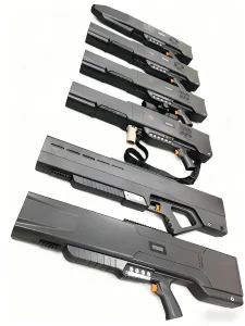
1. Defense & Anti-Drone Countermeasure Guns
RF power amplifiers operating across multi-band jamming frequencies (433MHz, 900MHz, 1.2GHz, 2.4GHz, and 5.8GHz) demand absolute signal purity and thermal dissipation. Our specialized hybrid PTFE/FR-4 multi-layer boards maintain consistent dielectric constants, withstanding sustained high RF power without dielectric breakdown or thermal drift.
2. Automotive BMS & Traction Inverters
High-voltage battery packs require extreme creepage and clearance distances, high CTI (Comparative Tracking Index > 600V) laminates, and heavy copper planes capable of carrying 200A continuous current. Our IATF 16949-aligned processes prevent micro-fissures under aggressive thermal-shock cycling (-40°C to +125°C).
3. Edge IoT Computing & Single-Board Computers
High-density platforms such as Raspberry Pi expansion HATs, industrial compute engines, and smart sensor hubs integrate high-speed LPDDR memory, Wi-Fi 6/BLE connectivity, and Power-over-Ethernet (PoE) in ultra-compact form factors. We deliver 6-to-10 layer microvia stackups with laser-trimmed impedance control.
4. Industrial Motor Drives & Smart Energy Grid
Switching transients in silicon carbide (SiC) and gallium nitride (GaN) motor drives generate aggressive dV/dt electromagnetic noise. Our fabrication enforces tight internal ground-plane shielding, low-inductance VIPPO design rules, and heavy copper thermal cores to sustain uninterrupted 24/7 factory automation operations.
Advanced Capabilities Catalog
High-TG, Heavy Copper & RF Microwave Board Selection
Specialized fabrication for extreme temperature profiles, high-wattage power supplies, and high-frequency microwave communications.




Technical & Sourcing Authority
Enterprise PCB Sourcing & Engineering FAQ
Comprehensive answers to critical technical, testing, pricing, and compliance inquiries posed by senior procurement and hardware engineering teams.
What specific design factors drive the biggest cost escalations on an OEM PCB pricelist?
The primary cost drivers beyond layer count are: (1) Blind and Buried Vias / HDI Lamination Cycles: Every sequential lamination cycle adds a complete heat-press, drill, desmear, and plating cycle, increasing fabrication time and scrap risk; (2) Panel Utilization: If your board dimensions result in poor nesting on standard working panels (e.g., 40% waste area on a standard 18x24 inch panel), you pay for unusable substrate; (3) Hole Size & Density: Mechanical holes < 0.2mm require specialized slow-feed drilling spindles, while holes < 0.15mm necessitate laser drilling; (4) Surface Finish Choice: ENIG and ENEPIG involve substantial chemical precious metal costs compared to Lead-Free HASL or OSP; and (5) Tight Trace/Space Tolerances: Line/space widths below 3/3 mil demand high-grade Laser Direct Imaging (LDI) and reduced etching speeds.
How does PCB ADEPT guarantee IPC Class 3 compliance versus standard IPC Class 2?
IPC Class 3 represents the highest operational standard, mandatory for mission-critical aerospace, military, and medical devices where operational downtime is intolerable. Our Class 3 builds enforce: (1) Minimum copper plating thickness inside through-hole barrels of 25μm (compared to 20μm for Class 2); (2) Zero annular ring breakout permitted, requiring expanded pad diameters during DFM; (3) Stricter internal layer misregistration tolerances; and (4) Mandatory micro-sectioning coupons polished and inspected under high-magnification microscopes per production panel to verify dielectric thickness, resin recess, and copper barrel integrity.
What is the difference between FR-4 Tg 150°C, Tg 170°C, and Tg 180°C, and when should High-Tg be specified?
Glass Transition Temperature (Tg) indicates the thermal point where the epoxy resin matrix transforms from a rigid glass-like state into a softened, rubbery material. Standard FR-4 has a Tg of 130–140°C. For multi-cycle lead-free soldering profiles (which peak between 245°C and 260°C), standard FR-4 undergoes high Z-axis thermal expansion, stressing plated copper barrels and causing barrel cracking. We recommend High-Tg (Tg ≥ 170°C, such as Shengyi S1170 or ITEQ IT-180A) for: (1) Any board with 6 or more layers; (2) Heavy copper power boards; (3) Automotive and industrial enclosures subject to elevated operating temperatures; and (4) High-reliability designs demanding resistance against Conductive Anodic Filament (CAF) growth.
How do you verify characteristic impedance control and what tolerances are standard?
We perform front-end electromagnetic field solver simulations (Polar SI9000) during DFM to calculate exact trace widths, ground plane spacing, and prepreg dielectric constants (Dk). During production, dedicated test coupons are positioned along the perimeter of each manufacturing panel matching the critical single-ended (50Ω) and differential pair (90Ω, 100Ω) geometries. We perform 100% Time Domain Reflectometry (TDR) testing, delivering signed impedance verification test reports with every shipment. While standard commercial tolerance is ±10%, our precision LDI and differential etching chemistry maintains tight ±5% precision upon engineering request.
How does PCB ADEPT protect against counterfeit electronic components during turnkey PCBA assembly?
Counterfeit mitigation is governed by our rigorous incoming quality control (IQC) protocol. We procure directly from original semiconductor manufacturers (TI, ADI, ST, Microchip, Murata) and franchised authorized distributors (DigiKey, Mouser, Arrow, Element14). For hard-to-find or legacy parts, components undergo incoming destructive and non-destructive testing: (1) High-magnification optical inspection checking package markings, pin indentation, and indent sanding marks; (2) Acetone wash testing to detect remarking and blacktopping; (3) Real-time X-ray inspection comparing internal die dimensions and wire bonding layouts against golden samples; and (4) XRF spectral analysis verifying lead-free leadframe alloy composition.
What file formats are preferred for manufacturing review, and how fast is DFM feedback provided?
We prefer comprehensive ODB++ archives, as they encapsulate layer stackups, drill tables, netlists, and component centroid coordinates without ambiguous translation layers. However, standard Gerber RS-274X accompanied by Excellon NC drill files, IPC-D-356 netlists, and complete Excel/CSV Bill of Materials (BOM) are fully supported. Our 24/7 CAM engineering desk delivers thorough DFM/DFA engineering feedback reports within 2 to 4 hours of submission.
What testing methodologies are implemented for complete Turnkey PCB Assembly (PCBA)?
Every PCBA production run follows a sequential validation pipeline: (1) 3D Solder Paste Inspection (SPI) measuring solder paste volume, height, and alignment immediately post-stencil printing; (2) Automated Optical Inspection (AOI) both pre-reflow and post-reflow detecting component presence, polarity, tombstoning, and solder bridging; (3) 3D X-Ray Inspection (AXI) inspecting hidden solder joints under BGA, QFN, and LGA pads for voiding percentages (maintained under 15%); (4) First Article Inspection (FAI) verifying component values with automated LCR testers; and (5) Functional Testing (FCT) utilizing custom test fixtures to flash firmware and validate real-world operational parameters.
Accelerate Your Hardware Production With Direct Factory Pricing
Upload your Gerber files and BOM. Our senior CAM engineering team will deliver a comprehensive DFM feasibility analysis and transparent production pricelist within 2 hours.
Submit Files for Immediate DFM Review