

Primary Production Capabilities
Mission-Critical Multilayer Substrates & Assemblies
Direct factory production lines for extreme currents, thermal management, high layer counts, and severe RF environments. Explore our foundational PCBA engineering configurations.

High-Quality 1-60 Layers Multilayer PCB
Request Factory Quote
OEM High-Quality Rigid Flex PCB (4-16 Layers)
Request Factory Quote
Low-Loss Precision RF & Microwave PCB (≥500MHz)
Request Factory Quote
High TG PCB for Automotive & Aerospace (TG150-TG300)
Request Factory Quote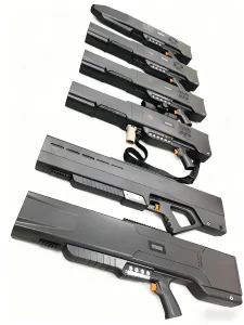
Specialized Anti-Drone Jamming Gun PCBA Modules
Request Factory Quote
High TG Defense Applications PCB (TG170-TG300)
Request Factory Quote
High Thermal Conductivity Aluminum Substrate PCB
Request Factory Quote
Industrial Status & Macro Environment
The Global Multilayer PCBA Paradigm: Engineering Complexity & Sourcing Realities
As electronic systems transition into multi-gigahertz operational domains, higher thermal density regimes, and aggressive micro-miniaturization, multilayer printed circuit board assembly has evolved from simple contract assembly into advanced materials science and algorithmic execution.
The international electronics manufacturing ecosystem in 2026 demands unprecedented integration. Global demand for multilayer PCB assembly (PCBA) spanning 4 to 60+ copper layers is accelerating at an annualized CAGR exceeding 7.8%, stimulated directly by hyperscale artificial intelligence datacenters, autonomous vehicle edge-compute controllers, commercial low-Earth-orbit (LEO) satellite communications, and localized high-density RF countermeasure systems. In this elevated technical landscape, purchasing professionals, lead hardware architects, and supply chain executives can no longer afford to treat raw PCB fabrication, active component procurement, and surface-mount technology (SMT) mounting as fragmented, transactional stages handled by isolated vendors.
Strategic Manufacturing Insight: Over 68% of post-reflow functional defects in multilayer assemblies originate from mismatched coefficients of thermal expansion (CTE), undetected inner-layer delamination during multi-zone thermal profiling, or microscopic solder voids under bottom-terminated components (BTC) and fine-pitch ball grid arrays (BGA). Shenzhen ICSLOVE Technology eliminates these integration failure points by unifying high-layer lamination, bare-board impedance testing, and precision SMT placement under one ISO 9001:2015 traceability infrastructure.
1–60
Rigid Layer Count Capability
01005
Micro-SMT Package Minimum
99.8%
Verified First-Pass Pass Rate
48 Hrs
Fast-Turn Multilayer Prototype
Located directly within Shenzhen's high-tech industrial epicenter (Anda Electronic Industrial Zone, Fuhai Subdistrict, Bao'an District), PCB ADEPT operates as the strategic global delivery arm of Shenzhen ICSLOVE Technology Co., Ltd. Backed by an established manufacturing footprint of 8,000 square meters, 6 automated high-speed SMT lines, and 4 dual-wave DIP lines, we address the critical pain point confronting international buyers: the friction, communication latency, and quality finger-pointing inherent in managing fragmented supply chains across disparate PCB board houses, independent component brokers, and secondary testing facilities.
Substrate Materials & Structural Architecture
High-Layer Count Engineering: Material Science Meets Tight Tolerances
From standard FR-4 laminates to exotic PTFE Rogers formulations and extreme heavy-copper configurations, our fabrication control parameters maintain uncompromising integrity across every dielectric layer.
Ultra-Dense 1–60 Layer Stacks
Controlled sequential lamination utilizing high-Tg prepreg materials (TG150, TG170, TG180, up to polyimide TG300). Inner layer core registration tolerances maintained within ±0.025mm using advanced X-ray target drilling and pinless induction bonding systems to eliminate layer slippage.
Heavy Copper Thermal Arrays
Engineered for high-current power converters, industrial drives, and automotive traction inverters. Copper thicknesses from 2oz to 12oz with optimized resin filling to ensure total encapsulation without micro-voids, supported by deep heat sink thermal dissipation vias.
RF & Microwave Hybrid Stacks
Seamless hybrid pressing of low-loss PTFE laminates (Rogers RO4350B, RO4003C, RO3003, Taconic series) with standard FR-4 cores. Tight impedance tolerances within ±5% for multi-gigabit signal traces and RF front-ends operating well beyond 500MHz to 77GHz millimeter-wave bands.
High-Density Rigid-Flex (4–22 Layers)
Dynamically flexible polyimide (PI) cores combined with rigid FR-4 sections, offering 4 to 22 structural layers. Incorporates laser-drilled blind and buried microvias, stiffeners in aluminum, stainless steel, and FR-4, with up to 4x HDI lamination cycles.
| Engineering Parameter | Standard Capability | Advanced / Extreme Capability | Quality Verification Method |
|---|---|---|---|
| Layer Count Range | 1 – 16 Layers | Up to 60 Layers (Rigid), 22 Layers (Rigid-Flex) | Cross-section Microsection Analysis |
| Minimum Line Width / Spacing | 3.0 mil / 3.0 mil (0.075mm) | 1.8 mil / 1.8 mil (0.045mm with mSAP) | Automated Optical Inspection (AOI) |
| Dielectric Core Glass Transition (Tg) | TG 150°C – TG 170°C | TG 180°C, TG 260°C, TG 300°C (Polyimide) | Differential Scanning Calorimetry (DSC) |
| Finished Copper Weight | 1oz – 3oz | 4oz – 12oz (Heavy Copper Fabrication) | Eddy Current & Chemical Micro-Etch |
| High Frequency Substrates | FR-4 High Speed (Shengyi, ITEQ) | Rogers, Taconic, PTFE Hybrid Lamination | TDR Impedance Coupon Testing (±5%) |
| Surface Finishes | HASL Lead-Free, Standard ENIG | ENEPIG, Hard Gold (30u"), Immersion Silver/Tin | X-Ray Fluorescence (XRF) Thickness Gauge |
| Microvia Laser Drilling Aspect Ratio | 0.8 : 1 (Blind / Buried) | 1 : 1 Any-Layer Interconnect (ELIC) | 3D X-Ray Inspection & SEM Microscopy |
Assembly Automation & Process Control
Micron-Precision Surface Mount (SMT) & Through-Hole (DIP) Execution
Even the most meticulously engineered bare multilayer board will fail if the solder interface lacks metallurgical integrity. Our Bao'an SMT center deploy Yamaha modular high-speed mounters calibrated for sub-micron accuracy.
Our surface mount environment operates under tight environmental controls, regulating temperature (22±2°C), relative humidity (40–60%), and electrostatic discharge (ESD) per ANSI/ESD S20.20 standards. Across our 6 automated SMT lines, every circuit undergoes a closed-loop sequence:
1. Solder Paste Inspection (SPI)
Inline 3D SPI evaluates solder paste height, volumetric area, bridge formation, and deposit alignment. Misprints are intercepted and automatically wiped prior to component placement, guarding the first-pass yield.
2. High-Speed Yamaha Mounting
Mounting platform handles micro passives down to 01005 chips, up to fine-pitch 0.3mm micro-BGAs, high-pin QFPs, and specialized connectors with vision-assisted theta and co-planarity alignment.
3. 10-Zone Reflow Thermal Profiling
Precise thermal zoning features nitrogen inerting atmospheres, eliminating oxidation on fine-pitch pads. Tailored soak and peak reflow profiles ensure zero delta-T across massive copper plane differentials.
4. Post-Reflow 3D AOI & AXI
3D Automated Optical Inspection inspects solder fillets, tombstones, and polarity markings. Crucial BGA and QFN balls undergo 3D Automated X-ray Inspection (AXI) to guarantee ball voiding stays well under 10%.
Application Engineering
Mission-Critical Deployment Scenarios for Multilayer PCBA
Different market sectors demand specialized reliability criteria, ruggedization, and regulatory documentation. Our manufacturing routes adapt precisely to operational constraints.
Anti-Drone & Defense Jamming
High-power RF countermeasure equipment requires dense hybrid PTFE/FR-4 multilayer substrates capable of continuous RF amplification without thermal drift. We assemble multi-channel RF driver stages with embedded copper coin heat sinks and direct board-level shield soldering.
Aerospace & Satellite Telemetry
Subject to severe vibration and thermal cycling (-55°C to +125°C), our high-Tg polyimide assemblies utilize ENEPIG surface finishes, Class 3 IPC-A-610 assembly standards, and polyurethane conformal coating to prevent outgassing and tin-whisker migration.
Automotive Powertrain & BMS
Battery Management Systems (BMS) and on-board chargers (OBC) demand 4oz–8oz heavy-copper multilayer traces with high dielectric isolation. Assemblies are fortified against damp heat exposure through selective potting and automated conformal coating lines.
High-Compute AI Edge & Servers
Handling PAM4 112Gbps differential signaling requires ultra-low loss laminates (Dk < 3.5, Df < 0.003). We implement back-drilled via stubs, back-plane Press-Fit connectors, and micro-BGA assembly with zero solder bridging under automated X-ray inspection.
Medical Diagnostic Instrumentation
From portable ultrasound arrays to wearable physiological sensors, we provide high-density interconnect (HDI) rigid-flex boards with biocompatible gold plating, full electrical kitting traceability, and ISO 13485 compliant handling protocols.
Industrial Robotics & Power Inverters
Designed for multi-year operating lifecycles in dirty, high-surge factory environments. We integrate mixed SMT and THT power modules, screw terminals, and pulse-tolerant transformer chokes with deep automated optical and ICT verification.
Integrated Value Chain
Macro Turnkey Solutions: Eliminating Hardware Execution Friction
PCB ADEPT acts as a single accountable partner. We bridge the dangerous chasm between bare Gerber design rules, active component procurement anomalies, and volume manufacturing readiness.
1. Algorithmic DFM / DFA Scrubbing
Before copper is imaged or stencils cut, our engineers run your design through Valor NPI checks. We evaluate component footprint pad extensions, solder mask clearances, via-in-pad thermal relief, and aspect ratios to stop assembly defects before they start.
2. Direct Component Chain-of-Custody
Counterfeit components remain the bane of modern electronics. Our Shenzhen procurement procurement team interfaces directly with authorized master distributors (TI, STMicroelectronics, ADI, Microchip, Murata, TE Connectivity). All incoming parts undergo IQC microscopic inspection, date-code matching, and decapsulation verification when required.
3. MES-Driven Lot Traceability
Our Manufacturing Execution System logs every PCB barcode against specific solder paste lots, reel batch numbers, placement feeder heads, reflow temperature records, and AOI inspection images. True root-cause analysis is achieved in seconds.
4. Box Build, Firmware & Functional Test (FCT)
Beyond board-level assembly, we fabricate custom CNC-milled or plastic injection enclosures, integrate wire harnesses, flash MCU/FPGA firmware, and execute bed-of-nails functional testing, burn-in aging, and customized protective retail packaging.
Horizon 2026–2035
Multilayer PCBA Technology Roadmap: The Next Decade of Density
As semiconductor node shrinks outpace standard circuit board topologies, the interconnect density boundary is blurring between substrate manufacturing and PCB assembly.
Substrate-Like PCB (SLP) & mSAP
Moving beyond subtractive etching towards modified semi-additive processes (mSAP), enabling trace widths and spacing down to 25/25 microns (≤1 mil). This allows ultra-dense smartphone and AR/VR spatial computing hardware architectures.
Embedded Passives & Active Dies
Embedding decoupling capacitors, resistors, and thin-film silicon dice inside inner dielectric core layers to free outer layer real estate, suppress ground-bounce noise, and drastically shrink loop inductance for ultra-high switching GaN FET power architectures.
Co-Packaged Optics (CPO) Thermal Interfaces
Next-generation 800G and 1.6T networking switches require co-packaged optical modules mated with multilayer glass-core and ceramic composite substrates, demanding placement accuracy tighter than ±5 microns and advanced low-temperature solder alloys.
Procurement Engineering
How to Audit & Buy Multilayer PCBA: The OEM Vetting Checklist
When contracting a Chinese PCBA partner, procurement teams must evaluate verified factory capabilities rather than superficial sales representations. Use this criteria to benchmark prospective suppliers.
| Evaluation Parameter | High-Risk Broker / Low-Tier Factory | PCB ADEPT / Shenzhen ICSLOVE Benchmark |
|---|---|---|
| Factory Ownership & Facility | Trading company without manufacturing equipment | Direct 8,000m² factory with 6 SMT lines and 4 DIP lines in Bao'an, Shenzhen |
| Quality System Certifications | Expired, generic ISO 9001 certificates or none | ISO 9001:2015 certified, UL94V-0 recognized, full RoHS & REACH compliance |
| Solder Paste Verification | Manual visual check with 2D sample microscope | 100% Inline 3D Solder Paste Inspection (SPI) with automatic reject tracking |
| BGA Solder Joint Verification | Sample visual check from edge angle only | 3D X-Ray Inspection (AXI) analyzing void percentage and micro-crack formation |
| BOM Procurement Transparency | Spot-market grey brokers; high risk of cloned chips | Traceable supply channels via original component manufacturers & tier-1 authorized distributors |
| Engineering DFM Support | Blind production directly from supplied Gerber data | Dedicated English-speaking CAM & Process engineers conducting comprehensive DFM & DFA review |
Advanced Hardware Catalog
Specialized Multilayer Fabrication & Turnkey Products
Explore our precision product spectrum spanning high TG substrates, high-frequency Rogers laminates, custom Raspberry Pi HAT expansions, and high-density HDI builds.
OEM High TG Automotive & Defense PCB (TG150-TG300)
Request Factory Quote
Low-Loss High-Frequency PCB for Minimal Crosstalk & EMI
Request Factory Quote
High-Density Interconnect (HDI) Multilayer PCB Solutions
Request Factory Quote
High-Quality Custom Raspberry Pi HAT SBC Expansion PCBA
Request Factory Quote
Custom 4-16 Layer Multi-Layer Rigid-Flex Circuit PCB
Request Factory Quote
ODM High-Frequency PCB for Low Signal Loss & Crosstalk
Request Factory Quote
Durable Rogers High TG PCB for Aerospace & Defense
Request Factory Quote
Precision High Frequency PCB Solutions for EMI Issues
Request Factory Quote
Technical & Commercial Knowledge Base
Frequently Asked Questions for B2B Multilayer PCBA Buyers
Get direct engineering answers regarding file submission, layer stack-ups, high-Tg materials, counterfeit mitigation, testing protocols, and volume lead times.
1. What technical documentation is mandatory to initiate a multilayer PCBA quote?
To provide an accurate, build-to-print DFM analysis and quotation within 24 hours, our engineering department requires: (1) Standard Gerber files (RS-274X) or ODB++ database containing all copper layers, solder mask, silkscreen, drill files, and precise edge outline; (2) A complete Bill of Materials (BOM) in Microsoft Excel format detailing Reference Designators, Manufacturer Part Numbers (MPN), primary manufacturer name, package footprint, and approved alternate components; (3) Centroid / Pick-and-Place (XY coordinates and rotation angle) file; and (4) Fabrication and assembly mechanical drawings highlighting dielectric stack-up thickness, impedance control requirements, surface finish specifications (e.g., ENIG 2u" gold / 120u" nickel), and functional test parameters.
2. How do you prevent inner-layer delamination during lead-free reflow in high-layer boards?
Inner-layer delamination during high-temperature RoHS lead-free reflow (peak 245°C–260°C) is prevented through three mandatory controls: First, we exclusively specify high-Tg prepreg and core materials (Tg ≥ 170°C, T288 > 30 minutes, CTE z-axis < 3.0%) with low moisture absorption coefficients. Second, prior to final solder printing, bare multilayer boards undergo controlled vacuum baking at 120°C for 4 hours to drive out ambient moisture that could otherwise vaporize and cause catastrophic explosive delamination (popcorning). Third, automated multi-zone reflow profiles are established with regulated ramp rates (< 2.5°C/sec) to eliminate steep thermal gradients between inner copper planes and outer surface signal layers.
3. How does PCB ADEPT guarantee component authenticity and prevent counterfeit ICs?
Our supply chain team implements a rigorous four-tiered verification framework. We procure directly through authorized franchised distribution channels (Digi-Key, Mouser, Element14, Arrow, Avnet) and verified direct manufacturer distribution agreements for Texas Instruments, Analog Devices, STMicroelectronics, and NXP. For all non-franchised hard-to-find components requested by the client, our incoming quality control (IQC) protocol executes 100% incoming inspection including packaging integrity audits, optical microscopic verification of top-surface markings and pin metallization, solvent resistance tests (acetone swab test) to detect remarking or blacktopping, and X-ray inspection to confirm original leadframe geometry and internal bond wire presence.
4. Can you handle hybrid stack-ups combining Rogers RF substrates with standard FR-4?
Yes. Fabricating hybrid multilayer stacks (e.g., 2-layer Rogers RO4350B or RO4003C bonded on top of a 4-to-8-layer FR-4 digital ground and power core) is a core capability. This architecture optimizes system economics by placing expensive low-loss, high-frequency hydrocarbon/PTFE ceramics exclusively on critical high-frequency microwave routing layers while retaining economical standard FR-4 for non-critical power distribution and digital IO layers. Our hydraulic vacuum lamination presses utilize specialized slow-ramp thermal profiles and customized prepreg bonding films to reconcile the differing thermal expansion coefficients and cure kinetics between dissimilar material systems.
5. What are your minimum package capabilities for fine-pitch SMT assembly?
Our Yamaha modular SMT lines comfortably mount passive discrete components down to 01005 (0.4mm x 0.2mm) and 0201 packages with absolute repeatability. For active semiconductor devices, we routinely assemble 0.3mm pitch micro-BGAs (Ball Grid Arrays), CSPs (Chip Scale Packages), 0.4mm pitch QFNs (Quad Flat No-Lead), and ultra-fine-pitch connectors. Precision is secured using electroformed laser-cut nickel-plated stencils with specialized nano-coatings to ensure clean paste release, followed by 100% 3D SPI and post-reflow automated optical inspection.
6. What standard lead times can international customers expect for prototypes vs. volume orders?
For rapid R&D prototyping (1 to 50 pieces of multilayer PCBA up to 8 layers), our standard turn-around is 3 to 9 business days once all BOM components are verified in-house, with emergency quick-turn bare-board fabrication expedited within 48 hours. For pilot runs and mass manufacturing (500 to 100,000+ units), standard lead time ranges between 2 to 4 weeks depending on component lead times and bare-board lamination cycle counts. We offer bonded inventory consignment and safety-stock programs in our Shenzhen warehouse to enable on-demand split shipments via DHL, FedEx, or international air freight.
7. How do you verify solder joint integrity beneath non-visible BGA and QFN thermal pads?
Visual inspection is physically impossible for bottom-terminated components. We deploy automated high-resolution 3D X-Ray Inspection (AXI) calibrated to measure ball sphericity, solder bridging, cold-solder crystallization, and void percentages inside every individual solder joint. Our process limits BGA voiding to well under 10% (substantially superior to the IPC-A-610 Class 3 benchmark of < 25%), ensuring superior thermal transfer and fatigue resistance under cyclic vibration. First Article Inspection (FAI) reports with included X-ray imagery are delivered prior to mass volume line release.
8. What testing services are available for completed multilayer assemblies?
We provide a comprehensive testing menu to guarantee out-of-the-box field reliability: (1) In-Circuit Testing (ICT) via bed-of-nails or flying probe to check for trace continuity, resistor values, and capacitor tolerances; (2) Boundary Scan (JTAG) to verify complex digital bus interconnects between BGAs and memory chips without physical test points; (3) Functional Testing (FCT) where custom-built test fixtures simulate real-world operational environments, checking current draw, signal waveforms, and logic states; (4) MCU / EEPROM firmware flashing; (5) Environmental Stress Screening (ESS) including temperature cycling (-40°C to +85°C) and burn-in aging; and (6) Conformal coating inspection under ultraviolet (UV) illumination.