
High-Quality High TG PCBs for Automotive and Aerospace - China Suppliers & Factory (TG150, TG170, TG180, TG260, TG300) Manufacturers, Company
Product Description
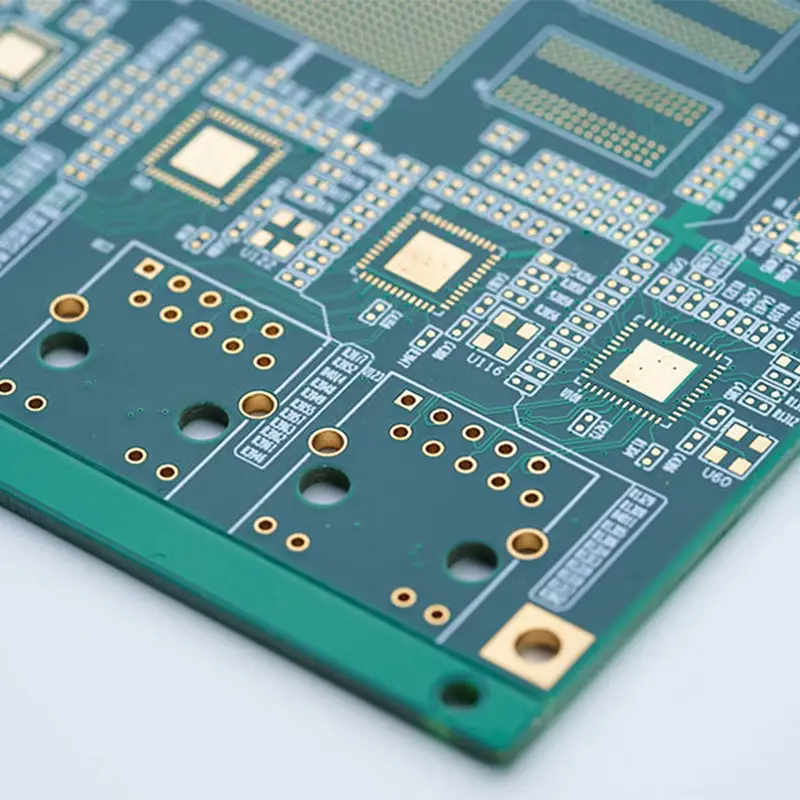
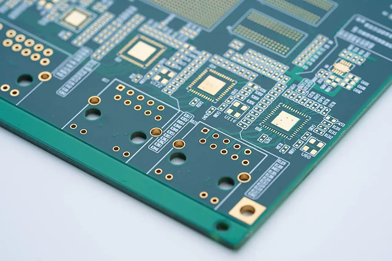
What Is High TG PCB?
Glass transition temperature: Tg is the abbreviation of "Glass transition Temperature". It is not the melting point of the material, but rather the critical temperature point at which a resin substrate (such as epoxy resin) transforms from a hard "glassy state" to a soft and elastic "rubber-like state". Below this temperature, the material maintains dimensional stability and mechanical strength. Above this temperature, the material begins to soften and its mechanical and electrical properties decline sharply.
High Tg PCB: Generally, PCB substrates with a Tg value of ≥ 150°C are defined as high Tg materials. The Tg of a conventional FR-4 is generally around 130-140℃.
Core Features
Super Heat Resistance
It can withstand the high temperature of lead-free welding (usually over 260℃), and the underlayment structure remains stable in high-temperature environments without problems such as delamination or deformation. For instance, in the soldering process, ordinary PCBS may soften and fail due to high temperatures, while high Tg PCBS can pass the 288℃ tin furnace test without any issues such as board explosion or copper foil peeling.
Stable Mechanical and Dimensional Properties
The coefficient of thermal expansion (CTE) is lower than that of conventional plates, which can reduce warping caused by temperature changes and prevent the copper layer at the through holes from cracking. This feature is particularly crucial in multi-layer boards of 8 layers or more, ensuring the reliability of the connection of the plated through holes.
Outstanding Electrical and Chemical Properties
Most high Tg plates have a low dielectric constant (such as 3.5±0.05@1GHz for some high-end models) and low dielectric loss (as low as 0.002), which can reduce high-frequency signal attenuation and crosstalk, and are suitable for high-speed signal transmission. At the same time, it has strong chemical resistance. Its performance remains intact even after wet treatment and immersion in chemical solutions. It can also withstand humid environments and is suitable for complex working conditions.
Common Materials
The boards of high Tg PCBS are mostly high-performance resin substrates. The Tg values of different materials vary greatly, adapting to the requirements of different scenarios. The common types are as follows:
| Material | TG Value |
|---|---|
| Rogers RO4350B | 280℃ |
| Rogers RO4003C | 280℃ |
| Alon 85N | 250℃ |
| Isola FR408HR | 180℃ |
| Weichuang6 | 185℃ |
Key Application Scenarios
Automotive Electronics
The BMS system of new energy vehicles, the ECU in the engine compartment, etc., tend to generate a large amount of heat during operation. High Tg PCBS can operate stably in this high-temperature environment, ensuring driving safety.
5G & High-Performance Computing
5G base station antennas, optical modules, as well as servers, switches and other equipment have extremely high requirements for high-frequency signal transmission. The low loss characteristic of high Tg boards can ensure signal integrity and improve data transmission efficiency.
Aerospace and Military Industry
Equipment such as satellite communication boards and polar environment radar control boards need to withstand extreme temperature differences ranging from -40 ℃ to 125℃. PCBS using substrates like TG180 can enhance thermal cycling tolerance and reduce failure rates.
Medical Electronics
Ultrasound imaging devices, high-temperature disinfected related medical equipment, rely on the stability of high Tg PCBS under high-temperature and long-term operation to avoid the impact of equipment failure on diagnosis and treatment.
Key Points of Manufacturing Process
Lamination Process
By using a precise temperature-pressure curve in combination with vacuum lamination technology, the board is bonded at a high temperature of around 180℃ and under a specific pressure to eliminate air bubbles, enhance Z-axis stability, and ensure the bonding strength between layers.
Drilling and Impedance Control
Laser drilling technology is widely used, with a hole diameter accuracy of ±25μm, suitable for micro-hole interconnection of multi-layer HDI boards. At the same time, impedance must be strictly controlled, with tolerances usually kept within ±5% to ensure high-speed signal transmission.
Surface Treatment
To prevent oxidation on the surface of high Tg plates, surface treatment methods such as tin plating and nickel-gold plating are preferred. In addition, a large solder mask window should be opened in the pad area to enhance the adhesion between the solder and the copper layer.
Frequently Asked Questions (FAQ)
Q: What is the difference between standard FR-4 and High Tg PCB?
Standard FR-4 typically offers a glass transition temperature (Tg) of 130°C to 140°C, while High Tg PCBs have a Tg value of 150°C or higher (such as 170°C, 180°C, or up to 280°C). High Tg boards provide superior thermal stability, lower thermal expansion rates (CTE), and higher mechanical durability during high-temperature operations.
Q: Why is High Tg essential for lead-free soldering?
Lead-free soldering processes usually reach temperatures above 260°C. Standard PCB materials may delaminate, bend, or experience copper peeling at these levels. High Tg PCBs easily pass stringent heat stress tests (like the 288°C tin furnace test) without material degradation.
Q: When should I choose a High Tg PCB design?
You should specify High Tg PCB when designing multi-layer boards (8+ layers), high-density HDI circuits, automotive systems (ECU/BMS), industrial high-power devices, aerospace equipment, or any application exposed to extreme thermal cycling.
Q: Does High Tg improve PCB signal transmission?
Yes. Many High Tg substrates provide lower dielectric constant (Dk) and lower dielectric loss (Df), which minimizes high-frequency signal attenuation and crosstalk, making them optimal for 5G and high-speed computing designs.
Q: Does Tg represent the maximum continuous operating temperature?
No. Tg indicates the transition phase from a rigid glassy state to a rubbery state. Generally, the maximum continuous operating temperature of the PCB should be kept at least 20°C to 25°C below the designated Tg rating for optimal reliability.









