
Featured High-Frequency & Multilayer Systems
Explore high-yield RF laminates, rigid-flex configurations, and specialized microwave solutions engineered to overcome phase jitter, crosstalk, and harmonic distortion.






The Macro-Industrial RF Paradigm: Physics, Economics & Fabrication
A rigorous industrial examination of RF substrate metallurgy, dielectric degradation mechanisms, and cost-containment frameworks across mission-critical RF/microwave procurement cycles.
In modern electronic systems operating from the sub-6 GHz telecom bands up to millimeter-wave (mmWave) regimes exceeding 77 GHz and 110 GHz, printed circuit boards cease to behave as passive mechanical interconnects. Instead, they transform into active, distributed-element transmission components where the physical morphology of the copper, molecular stability of the dielectric laminate, and microscopic uniformity of resin interfaces dictate overall signal integrity.
Global procurement teams navigating the sourcing landscape for a famous RF PCB manufacturing company must reconcile stringent microwave physics with high-volume economic constraints. Designing and manufacturing RF printed circuit boards requires solving three fundamental electromagnetic loss vectors: dielectric loss (governed by the loss tangent, tanδ or Df), conductor loss (governed by skin depth and copper surface profile RMS roughness), and radiation/dispersion loss (instigated by non-homogeneous dielectric constants, Dk, and microstrip phase mismatches).
Critical Engineering Insight: The Conductor Skin Effect in mmWave Regimes
At 10 GHz, electrical current flows primarily within a shallow 0.66-micrometer skin depth of the outer copper conductor. When standard standard electrodeposited (ED) copper with peak-to-valley roughness ($R_z > 5\,\mu\text{m}$) is utilized, the physical electromagnetic path length expands exponentially. This triggers prohibitive insertion losses and severe phase velocity dispersion. Industrial-grade RF fabrication mandates reverse-treated foils (RTF) or ultra-low profile (VLP/HVLP, $R_z < 1.2\,\mu\text{m}$) copper bonded to fluoropolymer (PTFE) or hydrocarbon ceramic matrix systems.
Global Enterprise Procurement: Navigating RFQ Dynamics & Yield Risks
Enterprise procurement executives within defense, telecommunications, and industrial radar verticals frequently encounter volatile quote variances—sometimes exceeding 300%—when soliciting quotes for RF and microwave PCBs. Understanding the cost architecture requires dissecting raw core substrate acquisition costs versus yield loss during multi-stage pressing and etching processes.
- Raw Material Cost Ratios: Premium microwave laminates such as Rogers RO4350B, RO3003, Taconic RF-35, or Nelco Meteorwave trade at 5× to 12× the square-meter cost of standard high-Tg FR-4 (e.g., Shengyi S1000-2M or ITEQ IT-180A). Substrate yield optimization is paramount during nesting and panel panel layout.
- Tight Dielectric Tolerance Control: Standard commercial PCBs permit a dielectric tolerance of ±10%. Conversely, RF beamforming or automotive radar networks require a rigorous Dk stability of ±0.02 to ±0.05 across continuous thermal bands (-40°C to +125°C), demanding precision lot qualification and thermal dielectric coefficient ($TcD_k$) verification.
- Etch Profile Fidelity (Trapezoidal Factor): In controlled-impedance lines ($50\,\Omega$ single-ended, $100\,\Omega$ differential), traditional chemical wet etching produces an undercut, causing an uncontrolled trapezoidal conductor geometry. Famous RF fabricators apply real-time optical chemical compensation and vacuum etching to maintain trace width tolerances within ±0.012 mm (±0.5 mil).
| Substrate System / Material | Dielectric Constant ($D_k$ @ 10 GHz) | Dissipation Factor ($D_f$ @ 10 GHz) | Thermal Conductivity (W/m·K) | Primary Industrial Application Target |
|---|---|---|---|---|
| Rogers RO4350B (Hydrocarbon/Ceramic) | 3.48 ± 0.05 | 0.0037 | 0.69 | 5G Cellular Transceivers, Power Amplifiers, Automotive Radar |
| Rogers RO3003 (PTFE/Ceramic) | 3.00 ± 0.04 | 0.0010 | 0.50 | 77–81 GHz Automotive ADAS Radar, mmWave Satcom Antennas |
| Taconic RF-35 (Organic/Ceramic PTFE) | 3.50 ± 0.05 | 0.0018 | 0.45 | Phased Array Antennas, Filter Networks, Anti-Drone RF Guns |
| Panasonic Megtron 6 (High-Tg Polyphenylene) | 3.71 ± 0.05 | 0.0020 | 0.40 | High-Speed Backplanes, High-Layer Cloud AI Switches, 112G PAM4 |
| High-Tg FR-4 (Industry Baseline) | 4.40 ± 0.15 | 0.0180 | 0.25 | Baseband Digital Control, Power Supply Modules, Peripheral Logic |
Macro-Industry Solutions & Engineered Stackup Topologies
How PCB ADEPT (Shenzhen ICSLOVE Technology) solves mission-critical transmission and integration hurdles across commercial, industrial, and defense domains.
Telecom 5G/6G & Active Antennas
Massive MIMO antenna arrays demand ultra-flat phase propagation and zero dielectric variation across large surface footprints. We fabricate 16-to-32 layer hybrid stackups pairing RO4350B signal layers with high-Tg FR-4 cores via Rogers 4450F bonding film, minimizing passive intermodulation (PIM < -160 dBc) while slashing bill-of-materials costs by 45% compared to monolithic RF lamination.
Counter-UAS & Anti-Drone Systems
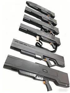
High-power RF jamming guns and drone spoofers operate at elevated pulsed and continuous transmission currents across multi-band sweeps (433 MHz, 900 MHz, 1.2 GHz, 2.4 GHz, and 5.8 GHz). By combining heavy copper (3 oz to 6 oz) power distribution layers with pure Taconic or Rogers high-frequency RF microstrip surfaces, our factory ensures exceptional thermal conductivity and zero solder-joint delamination during sustained RF power discharge.
Automotive mmWave ADAS (77–81 GHz)
Autonomous collision avoidance and adaptive cruise control radars rely on micro-wavelength accuracy where microstrip trace variances of 10 micrometers alter the beam reflection pattern. We utilize Rogers RO3003 coupled with laser direct imaging (LDI), plasma surface activation, and immersion silver (IAg) or ENEPIG finishes to preserve surface planarity and eliminate insertion losses caused by nickel skin resistance.
Technical Roadmap & High-Frequency Material Frontiers (2025–2035)
Engineering future-proof circuit interconnects for satellite mega-constellations, sub-terahertz processing, and co-packaged optics (CPO).
Liquid Crystal Polymer (LCP)
As operating frequencies trend toward 140 GHz (sub-terahertz 6G), traditional reinforced glass laminates suffer from the "glass weave effect"—where signals traveling over resin bundles versus glass fibers experience phase skew. LCP flexible substrates offer an ultra-flat, moisture-resistant ($< 0.04\%$) medium with isotropic Dk (2.9–3.0) ideal for bendable satellite antenna arrays and ultra-thin smartphone radar apertures.
Glass Substrates & CPO Co-Packaging
Silicon photonics and hyperscale AI accelerators running at 224 Gbps per lane mandate sub-micron interconnect precision. Our engineering roadmap integrates photo-imageable dielectrics (PID) and ultra-smooth glass core carriers that completely eradicate the conductor surface roughness penalties of traditional metal foils, lowering insertion loss below 0.4 dB/inch at 50 GHz.
Surface Finish Evolution: Beyond ENIG
Traditional Electroless Nickel Immersion Gold (ENIG) creates catastrophic RF attenuation at >10 GHz due to the high magnetic permeability ($\mu_r \approx 600$) and high electrical resistivity of the electroless nickel boundary layer. Our production replaces standard ENIG with Electroless Nickel Electroless Palladium Immersion Gold (ENEPIG) or Direct Immersion Gold (DIG) to establish flawless, non-magnetic wire-bondable and high-frequency conductor tracks.
Industrial Governance, Shenzhen Supply Chain & Compliance Assurance
Combining the agile component sourcing ecosystem of Shenzhen with rigorous ISO 9001 and IPC Class 3 quality execution.
Operating from our primary 8,000 m² production complex in Anda Electronic Industrial Zone, Fuhai Subdistrict, Bao'an District, Shenzhen, Shenzhen ICSLOVE Technology Co., Ltd. (PCB ADEPT) bridges the gap between fast-turn prototype agility and uncompromising international quality standards. Shenzhen represents the epicentre of global hardware innovation—housing key semiconductor hubs and major supply chain nodes that allow direct-from-factory procurement of genuine active components from Texas Instruments (TI), Analog Devices (ADI), STMicroelectronics, Microchip, and Murata passives within hours.
To eliminate cross-talk and RF assembly anomalies, our factory floor hosts 6 fully automated Yamaha SMT lines and 4 DIP lines linked directly to an intelligent Manufacturing Execution System (MES). Every panel is assigned a dynamic 2D matrix barcode that records raw substrate lot codes, lamination press cycle temperatures, solder paste volume measured via 3D SPI, and post-reflow optical verification from high-speed 3D AOI machines.
Frequently Asked Questions (RF Engineering & Quotes)
Authoritative technical and procurement guidance addressing critical questions posed by hardware architects and global sourcing directors.
Why is Electroless Nickel Immersion Gold (ENIG) discouraged for high-frequency RF applications above 10 GHz?
How does a hybrid multilayer PCB stackup reduce overall fabrication costs while preserving RF performance?
What parameters must be supplied in an RF PCB RFQ package to obtain a definitive 24-hour turnaround quote?
How does PCB ADEPT mitigate Passive Intermodulation (PIM) during RF circuit board processing?
What is the critical difference between woven glass reinforced PTFE and ceramic-filled hydrocarbon laminates?
How does your factory manage plasma surface treatment for PTFE/fluoropolymer substrates?
What are your minimum trace width, spacing, and drill-to-copper tolerances on high-frequency layers?
Can PCB ADEPT provide turnkey component sourcing for rare RF MMICs, power amplifiers, and couplers?
Advanced Multilayer, Flex & Specialized Hardware Solutions
Complete your supply chain integration with our full line of flexible interconnects, multilayer production runs, and field-tested tactical electronics.

Initiate Your RF & Microwave Engineering Review
Upload your Gerber X2, ODB++, or CAD layout alongside complete BOM documents. Our senior RF application engineers will perform a complimentary DFM analysis, stackup impedance validation, and provide an itemized production quotation within 24 hours.