Precision Engineered Rigid-Flex & Advanced PCB Portfolio
Explore our certified fabrication and turnkey assembly configurations engineered for ultra-compact enclosures, signal integrity, and dynamic endurance.





The Global Shift Toward Integrated Rigid-Flex Architectures
Analyzing modern electro-mechanical convergence: why mission-critical OEMs are abandoning traditional wire harnesses in favor of multi-dimensional rigid-flex circuitry.
Volumetric Packaging & Weight Reduction
Modern electronic devices in aerospace, military, and wearable medical sectors face severe spatial boundaries. Rigid-flex assemblies eliminate heavy multi-pin connectors, crimp terminals, and discrete wire harnesses. By uniting rigid functional sections (housing micro-BGAs and passive components) with ultra-thin polyimide flex cores, packaging space is reduced by up to 65% and payload mass by over 50%.
Superior Signal Integrity & High-Frequency Transients
Traditional connector-to-wire transitions cause severe impedance discontinuities, signal attenuation, and electromagnetic radiation. Rigid-flex circuits maintain unbroken ground planes and precisely engineered differential impedance (typically 90Ω or 100Ω ±5%) across rigid-to-flex transitions, making them indispensable for mmWave 5G/6G, anti-drone radar jamming, and ultra-high-speed data protocols.
Dynamic Flex Endurance & Harsh Environments
Engineered using adhesiveless Flexible Copper Clad Laminates (FCCL) and rolled annealed (RA) copper, rigid-flex substrates sustain millions of dynamic bending cycles without hairline micro-fractures. The complete encapsulation of polyimide coverlays guarantees immunity against thermal shock (-55°C to +150°C), sustained harmonic vibration, moisture ingress, and corrosive industrial atmospheres.
Material Science, Stack-up Physics & DFM Guidelines
A rigorous examination of rigid-flex manufacturing constraints, adhesive-induced z-axis expansion, and assembly tooling fixtures required for defect-free production.
FCCL Selection: Cast Adhesiveless vs. Adhesive Systems
Traditional modified acrylic adhesives exhibit a glass transition temperature (Tg) under 90°C and a high Coefficient of Thermal Expansion (CTE), often resulting in barrel cracking and delamination during 260°C lead-free reflow. PCB ADEPT deploys adhesiveless Polyimide (PI) laminates with directly deposited copper. Adhesiveless FCCLs reduce dielectric thickness by 40%, improve dynamic bending fatigue life by 300%, and ensure strict Z-axis dimensional stability through multiple lamination and soldering cycles.
Transition Zone Mechanics & Bead Control
The rigid-to-flex interface represents the focal point of mechanical shear and stress concentration. To eliminate trace fatigue, our DFM design rules enforce staggered conductor paths (avoiding I-beam effects where traces overlap on adjacent layers). Furthermore, we utilize no-flow or low-flow prepregs with precise laser pre-cut profiles to prevent resin starvation while ensuring resin bead overflow does not bleed more than 0.5mm into the dynamic flexing zone. Flexible epoxy fillet beading is selectively applied to distribute bend radius stresses away from rigid copper edge margins.
Thermal Profiles & Moisture Degassing Protocol
Polyimide is inherently hygroscopic, absorbing up to 1.5% to 3.0% ambient moisture by weight within hours of atmospheric exposure. If subjected directly to lead-free reflow temperatures (245°C–260°C), internal steam vaporization inevitably triggers explosive delamination and micro-voiding. Our SMT production lines enforce mandatory vacuum baking at 120°C for 4 to 6 hours prior to paste printing, followed by sealed transfer to our 6 Yamaha high-speed SMT lines under continuous Nitrogen-purged (N2) atmosphere reflow ovens.
| Manufacturing & Assembly Parameter | Standard Industrial Fit | Advanced / Mil-Aero Capability | Inspection & Verification Protocol |
|---|---|---|---|
| Rigid-Flex Layer Count | 2 to 10 Layers | Up to 22 Layers (4x Sequential HDI) | Cross-section microsectioning, X-ray laminography |
| Flex Base Core Thickness | 25μm (1 mil) to 50μm (2 mil) | 12.5μm (0.5 mil) Adhesiveless PI | Non-contact laser thickness measurement |
| Minimum Line Width / Spacing (L/S) | 3.0 mil / 3.0 mil (75μm / 75μm) | 2.0 mil / 2.0 mil (50μm / 50μm) | 3D Automated Optical Inspection (AOI) pre-lamination |
| Microvia / Mechanical Hole Minimum | 0.20mm (8 mil) Mechanical | 0.075mm (3 mil) UV Laser Microvia | Copper-filled via cross-section microscopy (SEM) |
| SMT Smallest Component Handling | 0201 passives, 0.4mm pitch ICs | 01005 passives, 0.3mm BGA pitch | In-line Solder Paste Inspection (SPI) & 3D post-reflow AOI |
| Dynamic Bend Endurance | Static installation only | >1,000,000 Dynamic Flex Cycles | Custom cyclic bend testing fixture (IPC-TM-650 2.4.3) |
| Surface Finishes Supported | Lead-free HASL, standard ENIG | ENEPIG, Hard Electrolytic Gold (30μin) | XRF plating thickness verification & solderability tests |
| Quality Standards & Class | IPC-A-600 / IPC-A-610 Class 2 | IPC-6013 Class 3, ISO 9001, RoHS, UL | 100% Flying Probe, MES traceability, FAI & FCT testing |
Shenzhen ICSLOVE Technology (PCB ADEPT) Operations
Combining state-of-the-art Japanese SMT pick-and-place automation with end-to-end MES tracking in the heart of China's premier electronics ecosystem.
Advanced 8,000 m² Facility in Bao'an
Located on the 5th Floor, Area B, Building 3, Anda Electronic Industrial Zone, Fuhai Subdistrict, Bao'an District, Shenzhen, our facility operates in close proximity to global component distribution centers and precision tooling fabricators. We house 6 fully automated Yamaha SMT lines, 4 specialized DIP through-hole lines, and dedicated cleanroom environments engineered to prevent particle contamination during flexible layer pressing.
End-to-End Traceable MES Architecture
Every single board and component lot is tracked by our proprietary Manufacturing Execution System (MES). From incoming raw material verification (IQC with optical inspection and XRF lead testing) to solder paste printing (in-line SPI), pre-reflow component alignment, post-reflow 3D AOI, First Article Inspection (FAI), and final Functional Testing (FCT), complete batch records are permanently archived under our ISO 9001 quality system.
Direct Component Sourcing & BOM Cost Down
Leveraging over a decade of supply chain relationships, our sourcing division procures factory-direct active components from global semiconductor leaders including Texas Instruments (TI), Analog Devices (ADI), STMicroelectronics, Microchip, Murata, and TE Connectivity (Tyco). We provide engineering drop-in replacement suggestions to overcome long-lead crises, achieving an average 10%+ BOM cost-down while maintaining 100% electrical equivalency.
Ready to Accelerate Your Rigid-Flex Engineering Cycle?
Send your Gerber RS-274X or ODB++ files alongside your structured BOM. Our senior DFM engineers will conduct a full design review, evaluate bend radius calculations, verify stack-up impedance, and return a comprehensive technical feasibility report within 24 hours.
Mission-Critical Sector Deployments
Rigid-flex assemblies developed by PCB ADEPT power next-generation defense systems, medical robotics, avionics, and high-density industrial electronics.
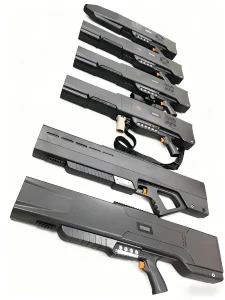
Counter-UAS & Anti-Drone Jamming Systems
Unmanned Aerial System (UAS) jamming equipment requires extreme RF output power across broadband microwave spectrums (400MHz to 6GHz). Our hybrid stackups blend Rogers/Taconic PTFE high-frequency laminates with multi-layer polyimide flex tails. This allows the RF power amplifier, FPGA controller, directional antenna, and cooling heatsinks to coexist in a single ultra-compact, high-vibration resistant chassis.
Class III Diagnostic & Surgical Medical Devices
In ingestible endoscopy cameras, cardiac mapping catheters, and wearable patient monitors, space is measured in cubic millimeters. Our micro-flex builds deploy 0.5 mil adhesiveless polyimide substrates loaded with 01005 passives and 0.3mm fine-pitch BGAs. Complete biocompatibility, lead-free RoHS compliance, and vacuum-sealed packaging ensure clinical sterility and unmatched electrical safety.
Automotive EV Battery Management Systems (BMS)
Electric vehicle battery packs demand continuous multi-channel cell voltage and temperature monitoring under intense thermal cycling and road vibration. Rigid-flex circuitry acts as a monolithic busbar interconnect, replacing hundreds of individual wiring terminations. Integrated thermal sensors, overmolded connectors, and copper-plated current paths ensure fail-safe performance across 15+ year automotive lifecycles.
Rigid-Flex Technology Roadmap (2025–2035)
Anticipating the technological frontier: how semiconductor packaging trends and ultra-high frequency requirements are transforming interconnect manufacturing.
Modified Semi-Additive Processing (mSAP)
While standard subtractive chemical etching encounters physical limitations at 40μm line/space due to trapezoidal undercut profiles, PCB ADEPT is transitioning to mSAP technology for flex layers. By starting with ultra-thin seed copper (1.5μm to 3μm) and pattern-electroplating straight rectangular copper sidewalls, trace geometry achieves sub-20μm conductor widths, enabling silicon-like interposer routing directly onto flexible polyimide.
Liquid Crystal Polymer (LCP) Core Adoption
For applications operating in the 77GHz–110GHz range (automotive autonomous radar and sub-THz satellite links), even high-end polyimide suffers from dielectric loss (Df ~ 0.008) and moisture sensitivity. LCP substrates provide a near-hermetic moisture absorption rate (<0.04%), a steady dielectric constant (Dk 2.9), and dissipation factors down to 0.002, matching pure PTFE while maintaining excellent thermoplastic bondability for multi-layer rigid-flex stacks.
Embedded Passives & Thin-Film Dies
The boundary between PCB assembly and IC substrate packaging is rapidly dissolving. Future rigid-flex topologies will embed thin-film resistors and planar capacitors directly inside inner flexible layers, freeing up 100% of the external board surface for active microprocessors and optoelectronic transceivers. Our engineering R&D group is actively validating Cavity Lamination and Z-axis Conductive Paste interconnect technologies for commercial deployment.
Rigid-Flex Assembly Critical Knowledge Base
In-depth technical answers addressing the most critical design, quality, and manufacturing questions encountered by overseas hardware engineering teams.
How do you calculate minimum bend radius for single-layer, double-layer, and multi-layer flex sections?
According to IPC-2223 design standards, the minimum bend radius (R) depends on whether the installation is static (flex-to-fit) or dynamic (continuous flexing) and total flex thickness (T):
- Single-Sided Static Flex: R = 6 × T (typically minimum 1.0mm to 1.5mm bend radius).
- Double-Sided Static Flex: R = 10 × T. Conductors should be placed on the neutral mechanical axis to balance compression and tensile forces.
- Multi-Layer Dynamic Flex (3+ Layers): R = 20 to 40 × T. Dynamic flex designs should ideally be restricted to 1 or 2 flexible layers using rolled annealed (RA) copper foil aligned along the natural grain direction of the web.
What specialized carrier fixtures are required to run flexible panels through SMT pick-and-place lines?
Flexible tails and thin rigid-flex panels lack the structural rigidity required for high-speed automatic pick-and-place nozzle pressures and reflow convective drafts. PCB ADEPT designs precision CNC-machined synthetic stone (Durostone/Ricocel) or anodized aluminum magnetic carriers. Panels are locked flat using high-strength neodymium magnetic clamping bars or silicone vacuum channels. This ensures absolute coplanarity within ±0.05mm, preventing tombstoning, solder bridging, and misplaced passives down to 01005 chips.
How does PCB ADEPT guarantee 100% genuine components and prevent gray-market counterfeits?
Our centralized procurement office has operated in Shenzhen for over 10 years, sourcing exclusively via authorized franchise distributors (Digi-Key, Mouser, Arrow, Avnet) or directly from original component manufacturers (TI, ADI, ST, Microchip). All incoming reels pass through strict IQC inspection: 100x optical marking verification, acetone swab wipe testing (detecting package remarking), pin lead co-planarity inspection, and destructive decapsulation verification when high-risk broker parts are mandated by clients during global component allocations.
Why is cross-hatch copper shielding preferred over solid copper planes on flexible signal runs?
Solid copper planes on flex layers significantly increase bending stiffness, induce severe spring-back forces, and create wrinkling or micro-delamination under continuous cyclic flexing. A 45-degree cross-hatched ground plane (typically 50% to 65% copper opening) preserves flexible fatigue life and flexibility while maintaining essential RF return paths and controlled impedance. When ultra-strict shielding is required, silver conductive ink film or vapor-deposited electromagnetic shielding films (e.g., Tatsuta SF-PC) are applied over the polyimide coverlay.
What test methods are performed to validate high-reliability rigid-flex assemblies before shipment?
We execute multi-tier electrical and physical testing: 100% netlist Flying Probe electrical testing on bare boards, Time Domain Reflectometry (TDR) for controlled impedance traces (±5%), 3D Solder Paste Inspection (SPI), pre- and post-reflow 3D AOI for solder fillet geometry, 2D/3D X-ray inspection for BGA voiding (guaranteed <10% void ratio per IPC-A-610 Class 3), and custom functional circuit testing (FCT) including burn-in thermal chamber cycling (-40°C to +85°C) and custom microcontroller firmware programming.
High-Frequency, RF Microwave & Multi-Layer Board Solutions
Explore our specialized industrial capabilities encompassing drone jamming RF modules, thermal aluminum metal cores, and high-layer count quick-turn PCBAs.