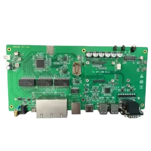
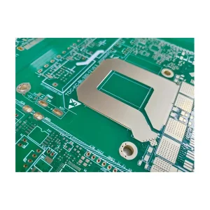
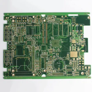
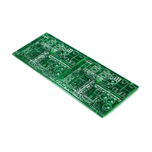
Specialized Rigid, Flex & High-Frequency Circuitry
Pre-qualified interconnect solutions manufactured to tight spatial and mechanical tolerances. Directly connect to engineering quotes below.
Engineering Principles of Rigid-Flex Interconnects
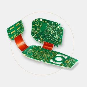
Rigid-flex printed circuit boards represent the apex of 3D spatial interconnect engineering. By permanently merging flexible polyimide substrates with high-Tg FR-4 rigid panels, OEMs eliminate physical board-to-board connectors, reduce enclosure profiles, and eradicate assembly failure vectors.
Substrate Thermodynamics
We deploy adhesiveless base copper-clad laminates (polyimide with electro-deposited or rolled-annealed foil) to eliminate adhesive squeeze-out defects and prevent delamination under lead-free reflow thermal cycles exceeding 260°C.
Dynamic vs Static Bending
Flexible regions are precision-engineered according to bend ratio (r/h). For static "flex-to-fit" builds, bend ratios are maintained at ≥10:1, while continuous dynamic flexing applications utilize balanced symmetrical neutral axis calculations with ≥20:1 ratios.
Controlled Impedance Integrity
Cross-hatch versus solid copper shielding geometries are calculated via 2D field solvers. We achieve stable ±5% single-ended and differential line impedance across transition interfaces between rigid fiberglass and polyimide layers.
Shenzhen Supply Chain Agility: From Prototype to Volume
Global original equipment manufacturers often face catastrophic delays when managing fragmented vendors across PCB fabrication, component procurement, and SMT assembly. Situated in Bao'an District, Shenzhen—the epicenter of global electronics manufacturing—our facility resolves cross-border procurement vulnerabilities.
- Hyper-Localized Material Sourcing: Direct tier-1 access to specialized substrates from Shengyi, ITEQ, Rogers, Taconic, and Panasonic Megtron within a 50km radius.
- BOM Risk Mitigation & Cost Reduction: Institutional relationships with franchised semiconductor distributors for TI, STMicro, Microchip, and Murata, securing authentic parts with 10–15% cost optimization.
- Unified Accountability: A single contract covers Gerber validation, custom lamination, component kitting, 3D AOI inspection, and box build integration under one roof.
Rigid-Flex Manufacturing Capabilities & Process Tolerances
Standard and advanced manufacturing tolerances calibrated to IPC-6013 Class 3 and IPC-A-600/610 requirements.
| Manufacturing Parameter | Standard Capability | Advanced / Extreme Precision | Verification & Test Standards |
|---|---|---|---|
| Layer Count Combinations | 4–16 Layers (Rigid-Flex Hybrid) | Up to 22 Layers (Rigid-Flex) / 60 Layers (Rigid) | Cross-section microsectioning, X-ray alignment |
| Base Materials | Polyimide (PI), FR-4 (Tg 150-170°C), Aluminum Base | Rogers RO4350B/RO3003, Taconic, PTFE, High-Tg FR-4 (180°C+) | DSC, TMA, IPC-TM-650 delamination testing |
| Min. Trace Width / Spacing | 3.0 mil / 3.0 mil (0.075mm) | 2.0 mil / 2.0 mil (0.050mm) | Automated Optical Inspection (AOI) with CAM laser check |
| Microvia / Laser Drill Diameter | 0.15mm (6 mil) | 0.075mm (3 mil) UV Laser Microvia | Microvia plating aspect ratio analysis ≥ 1:1 |
| Coverlayer Registration | ±0.05mm | ±0.025mm (Laser skiving & CNC routing) | Optical overlay comparator, solder flow barriers |
| Surface Finishes | Lead-free HASL, ENIG (Electroless Nickel Immersion Gold) | ENEPIG, Hard Gold (30-50 u"), Immersion Silver, OSP | XRF plating thickness audit per ASTM B568 |
| Impedance Accuracy | ±10% Nominal | ±5% Differential / Single-Ended | Polar TDR (Time Domain Reflectometry) test coupon verification |
| Flex-to-Rigid Transition Zone | 0.50mm clearance between coverlay and drill | 0.30mm with stress-relief strain relief bead | IPC-6013 Class 3 adhesion peel strength validation |
Global Standards & Localized Traceability Assurances
Meeting the exacting regulatory frameworks of North American, European, and Asian aerospace, medical, and automotive markets through unbroken supply-chain transparency.
ISO 9001 & IATF 16949
Production operations follow strictly documented APQP, PPAP, and FMEA protocols. Traceability from raw copper-clad lot numbers to final SMT reel barcodes.
IPC Class 3 & Mil-Spec
Full compliance with IPC-6013 for flexible prints and IPC-A-610 Class 3 for electronic assemblies. Zero-defect tolerance for life-support and mission-critical systems.
UL 94V-0 & RoHS/REACH
All flexible adhesive bonds, soldermasks, and rigid cores carry UL 94V-0 flammability certificates. Halogen-free and 100% compliant with EU RoHS and REACH regulations.
MES Digital Logging
Integrated Manufacturing Execution Systems record reflow temperature graphs, AOI optical captures, and functional testing outputs for up to 10 years for every serial batch.
Field Applications & High-Reliability Implementations
Where conventional wiring harnesses fail under vibration, weight constraints, and tight volumetric profiles, our rigid and flexible printed circuits deliver uninterrupted signal integrity.
Medical & Diagnostic Robotics
Endoscopic camera probes, ultrasonic transducers, and implantable monitoring arrays rely on our biocompatible polyimide flex circuits. Ultra-fine microvias and ENEPIG surface finishes guarantee corrosion immunity against aggressive bodily sterilization chemicals.
Aerospace & Anti-Drone Systems
In telemetry links, RF power jammer modules, and satellite phased-array antennas, high-frequency Rogers/FR-4 hybrid rigid-flex designs withstand extreme mechanical g-shocks and thermal excursions from -55°C to +150°C without micro-cracking.
Automotive EV Battery Management (BMS)
Heavy copper rigid-flex boards streamline prismatic battery cell voltage sampling and current measurement. Integrated NTC thermistors eliminate hundreds of crimped wires, reducing weight by 45% and eliminating connector oxidation risks.
Technological Horizons: HDI Any-Layer & High-Frequency Hybrids
As portable electronic devices pack multi-gigahertz processors into millimeter-thin enclosures, rigid-flex manufacturing is evolving toward micro-pitch and low-loss substrates.
HDI Any-Layer Integration
Integrating stacked microvias (via-in-pad plated over, VIPPO) directly within both the rigid and flexible inner layers allows 0.4mm pitch BGAs to escape cleanly without stub-induced signal reflections.
Substrate-Like PCB (SLP) Processing
Employing semi-additive process (mSAP) lithography enables ultra-dense line width/spacing down to 25/25 μm, enabling wearable AI processors and compact optical modules to operate with high routing density.
Low Loss Microwave Substrates
Adopting Liquid Crystal Polymer (LCP) and fluoropolymer films alongside rolled annealed copper delivers ultra-low dielectric constant (Dk 2.9) and dissipation factor (Df 0.002) for 60GHz+ mmWave and radar telemetry.
Frequently Asked Questions: OEM Rigid & Flex PCBs
Detailed technical answers to common queries submitted by hardware design engineers and procurement teams.
What is the key difference between adhesiveless and adhesive-based flex cores?
Adhesive-based polyimide uses an acrylic or epoxy bonding film to laminate copper to the base polyimide film. This introduces a thicker dielectric, higher moisture absorption (up to 3%), and lower thermal resistance. In contrast, adhesiveless polyimide (cast or direct-plated copper) provides superior thermal performance, better flexural endurance, lower Z-axis thermal expansion, and is required for high-reliability lead-free reflow and fine-pitch HDI routing.
How do you calculate the minimum bend radius for a rigid-flex PCB?
The minimum bend radius is governed by the total thickness of the flexible section (h) and whether the application is static or dynamic. For 1-2 layer static (flex-to-fit) applications, minimum bend radius R ≥ 10 × h. For multilayer static applications, R ≥ 20 × h. For continuous dynamic flexing applications, R should be ≥ 30–40 × h, with single-sided rolled annealed (RA) copper placed strictly on the neutral bend axis to avoid compression wrinkles or tensile fractures.
Why is polyimide coverlay preferred over flexible liquid photoimageable (LPI) soldermask?
While flexible LPI soldermask offers tight registration for fine-pitch SMT pads, it has limited mechanical ductility and micro-fractures under dynamic repetitive flexing. Polyimide coverlay (a solid polyimide film bonded with thermal acrylic adhesive) provides unmatched dielectric breakdown voltage, flame resistance, and mechanical tensile elasticity required to survive repeated bend cycles without cracking.
How do you handle DFM verification for the rigid-to-flex transition zone?
The interface where the flexible substrate enters the rigid FR-4 laminate is subject to localized shear stress. Our DFM rules enforce a minimum 0.50mm spacing between plated through-holes and the rigid edge, stagger transition interfaces by 0.20mm across adjacent layers to eliminate stress concentrations, and incorporate silicone or polyurethane strain relief fillets along the rigid boundary to prevent conductor fatigue.
What documentation and Gerber layers are required for an accurate rigid-flex quote?
An optimal package includes RS-274X or ODB++ files with clear outer boundary routing, an explicit flex-zone identification layer, a separate drill drawing indicating plated vs unplated vias, an unambiguous cross-sectional layer stack-up drawing defining dielectric thicknesses and copper ounce weights, stiffener placement definitions, and a detailed Bill of Materials (BOM) with manufacturer part numbers for assembly.
Can you assemble mixed-technology rigid-flex boards (fine-pitch BGA + heavy through-hole)?
Yes. We utilize precision CNC-machined magnetic carrier pallets that maintain planarity across the flexible windows during solder paste printing and SMT placement. Our 6 automated SMT lines support components down to 01005 passives and 0.35mm micro-BGAs, backed by dual 3D SPI and post-reflow 3D AOI inspection, supplemented by selective wave soldering for heavy DIP connectors.
What is the typical prototype and production lead time from your Shenzhen factory?
Standard prototype builds for 4-to-8 layer rigid-flex bare boards require 5 to 9 working days, with 72-hour fast-track options available for mission-critical cycles. Turnkey PCBA prototypes (including component sourcing) are completed within 7 to 14 days. Volume production orders typically ship in 3 to 4 weeks depending on panel complexity and testing requirements.
How do you verify the authenticity of active ICs and passive components?
Our IQC team performs rigorous incoming component inspections. We inspect reel packaging, verify manufacturer label 2D matrix codes, check date code consistency, perform decapsulation and die inspection where counterfeit risk is flagged, and run solderability testing on our component inventory before releasing kits to SMT feeders.
Explore Additional Manufacturing Lines & Boards
Full-spectrum interconnect production covering heavy copper power distribution, HDI rapid prototyping, and complex multilayer boards up to 60 layers.