

ODM Heavy Copper PCB for Power Converters - High Current Capacity, Excellent Heat Dissipation | China Suppliers & Factory Manufacturers, Factories
Product Description
What is Heavy Copper PCB?
Core Features & Application Scenarios
- Strong current-carrying capacity: The current-carrying capacity of 70μm copper foil (2 oz) is approximately twice that of 35μm copper foil (1 oz) under the same line width.
- Good heat dissipation: The thick copper layer can quickly conduct heat, reducing the risk of overheating of the device.
- High mechanical strength: Thick copper enhances the PCB's resistance to bending and impact.
- Power converters (AC-DC / DC-DC)
- BMS for new energy vehicles
- Industrial frequency converters
- Control boards for welding machines
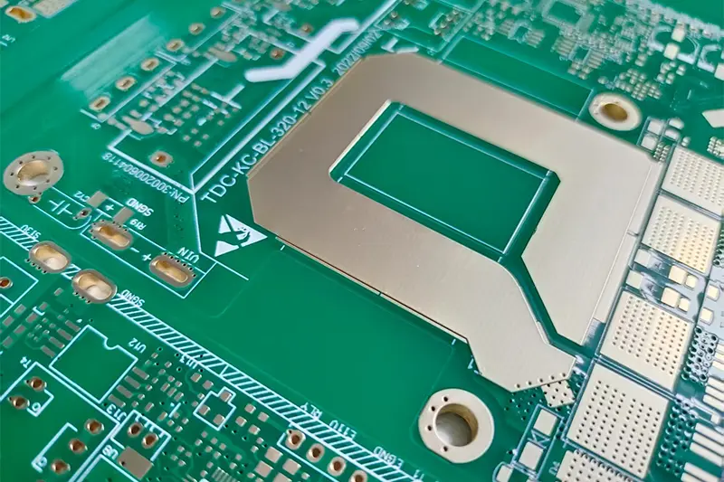
Key Design Points
Common specifications: 70μm (2 oz), 105μm (3 oz), 140μm (4 oz), up to 420μm (12 oz) in extreme scenarios.
Matching scenarios:
• Large current (≥5A): prefer 2–4 oz copper.
• Ultra-power (≥20A): select 6–12 oz copper.
Current-carrying calculation: Combine copper thickness, line width, and temperature rise (typically designed for ΔT = 10℃).
Formula: I = K × W × T0.83
Example: 2 oz (70μm), wire width 5mm → ~15A capacity at ΔT 10℃.
Trace optimization: Keep high-current traces as short and wide as possible; avoid narrow necks. Multi-layer boards can use parallel copper foil layers (2× 2 oz = 4 oz equivalent).
Vias: Increase hole diameter (≥0.5mm); increase via count (~1A per hole); copper plating thickness ≥20μm on hole wall.
Pads: Enlarge pad size by 0.2–0.5mm vs. standard pads to prevent false soldering caused by rapid heat dissipation during welding.
Heat dissipation: Design thick copper area as a "copper sheet heat sink"; add metallized via arrays (via spacing ≤1mm) to connect to the heat dissipation layer.
Insulation: Widen wire spacing for thick copper layers (for 70μm copper, spacing ≥0.2mm) to prevent creepage breakdown under high voltage.
Manufacturing Process Difficulties & Control
Thick copper lamination: High-temperature and high-pressure lamination (180℃ / 4MPa) is required to ensure peel strength between copper foil and substrate (≥1.2N/mm).
Thick copper etching: The etching rate is slow (~1μm/min). Etching time must be controlled to avoid side etching (side etching ≤0.05mm). A stepwise etching process should be adopted to reduce line width deviation.
The coefficient of thermal expansion (CTE) of thick copper layers differs significantly from the substrate. A symmetrical structure (consistent copper thickness between upper and lower layers) should be adopted during lamination, and a rigid support layer should be added to prevent PCB warping (warping degree ≤0.5%).
The surface of thick copper is prone to oxidation. It is preferred to choose tin plating (high-temperature tin layer) or nickel-gold plating to avoid OSP (incomplete organic film coverage).
The pad area needs to be enlarged with a "solder mask opening window" to ensure sufficient bonding force between the solder and thick copper.









