
OEM Rapid PCB Prototyping and Validation by Leading China Suppliers and Factories for Modern Electronics Pricelist, Factories
Product Description
Looking back at the history of the electronics industry, PCB manufacturing was once a lengthy and painful bottleneck.
-
▶
The Manual Era (Mid-20th Century): In the early days, circuits were built using "point-to-point" wiring, which was bulky and unreliable. The advent of PCBs was a major step forward, but the process relied entirely on manual drafting, film exposure, and chemical etching. An iteration cycle could take weeks or even months.
-
▶
Standardization and the CAM Era (Late 20th Century): With the development of Computer-Aided Manufacturing (CAM) technology, the Gerber format became the standard, enabling the initial digital separation of design and manufacturing. However, the process still required physical film and tooling (e.g., drilling NC programs), remaining cumbersome.
-
▶
The Rapid Prototyping Revolution (Early 21st Century – Present): The internet, Laser Direct Imaging (LDI), automated precision drilling, and standardized materials gave rise to specialized quick-turn PCB services. Through online ordering, automated production lines, and efficient logistics networks, they have compressed PCB prototype lead times from "weeks" to "days," fundamentally changing the game.

The value of rapid prototyping lies not just in its speed, but in how it empowers the entire validation process.
Modern rapid prototyping is enabled by several key technologies:

Laser Direct Imaging (LDI)
Replaces physical film by using a laser to image the photoresist directly, offering high precision, speed, and adaptability for small-batch, high-mix production.

Automation and Digital Workflows
From Automated Optical Inspection (AOI) to flying probe testing and automated material handling, these processes minimize manual intervention, increasing efficiency and consistency.

High-Performance Materials
A wide range of materials, from standard FR-4 to high-frequency/low-loss (e.g., Rogers), high-Tg, and flexible substrates (PI), meets the rapid needs of diverse applications.

Online Collaboration Platforms
Customers submit Gerber files online, and the system automatically performs DFM analysis and provides instant quotes, streamlining the ordering process.
Modern rapid prototyping is enabled by several key technologies:
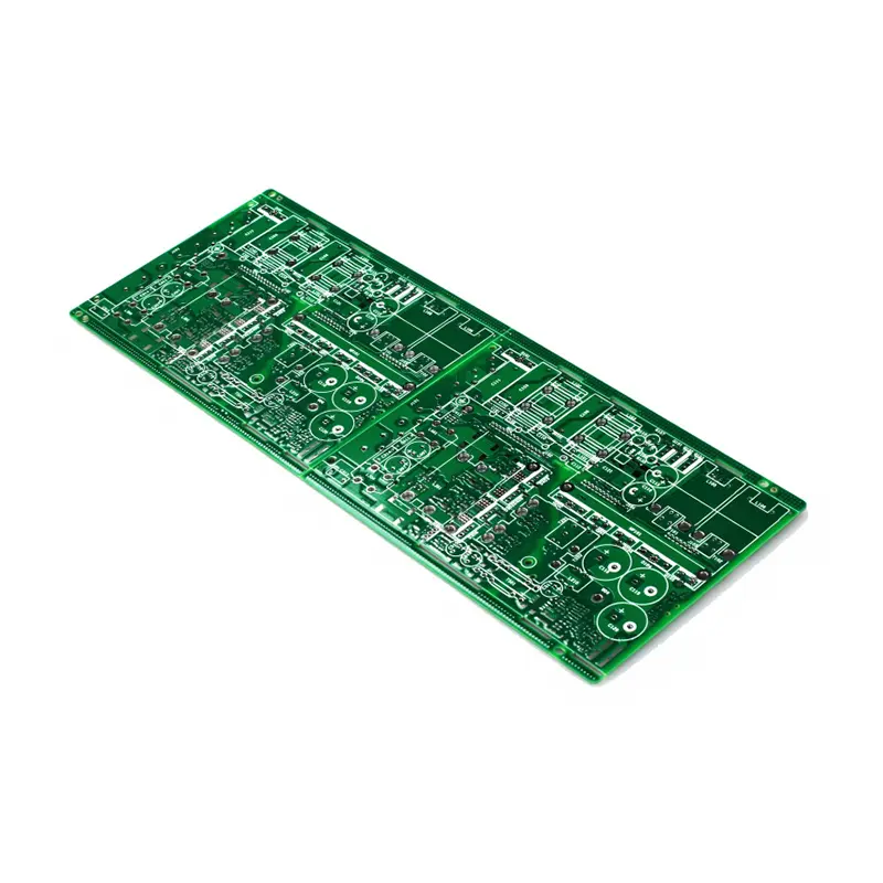
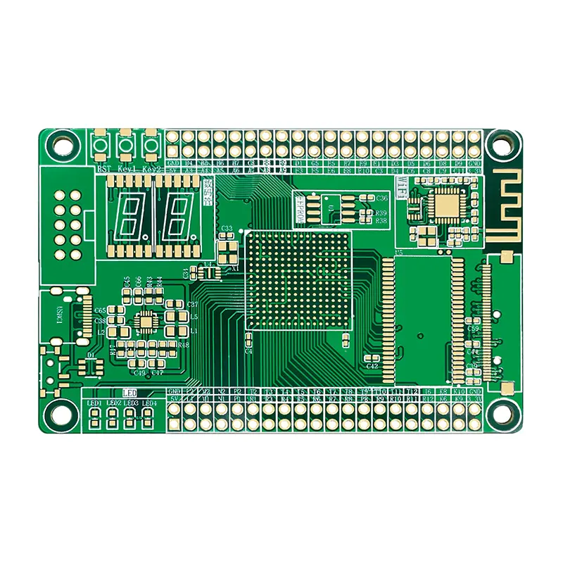
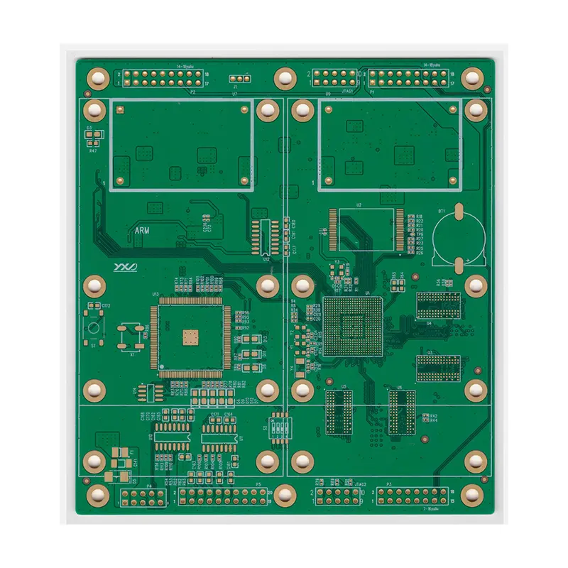
| Image | PCB Type | Description | Key Parameters |
|---|---|---|---|
|
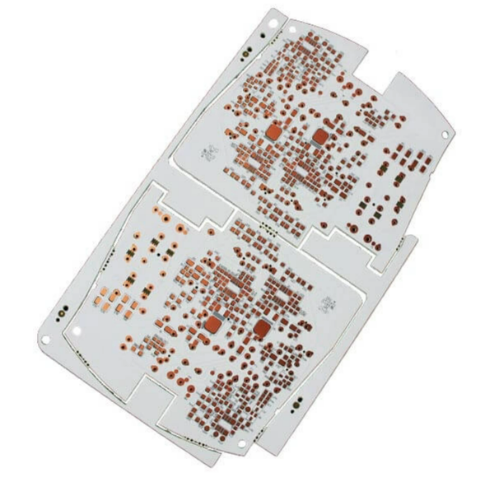
Single-Sided | Lowest cost, simple structure. Used in low-density consumer electronics. | Board Thickness: 1.0mm, 1.6mm Copper Weight: 1oz (35μm) Min. Trace/Space: 0.2mm |
|
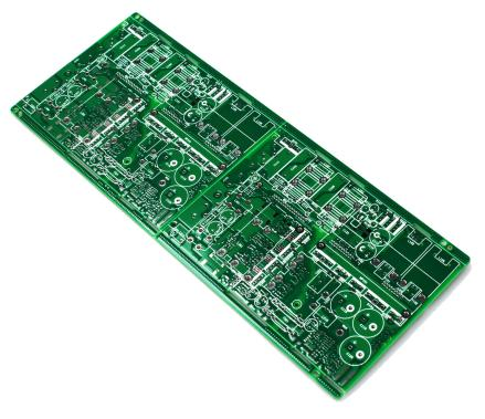
Double-Sided | The most common type, routing on both sides. Used in most standard electronic products. | Board Thickness: 1.0mm, 1.6mm Copper Weight: 1oz / 1oz Min. Trace/Space: 0.15mm / 0.1mm Vias: Mechanically drilled, hole size ≥0.3mm |
|
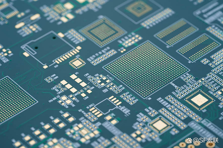
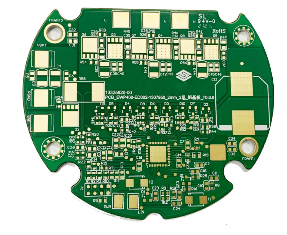
Multi-Layer | High density, high performance. Used in complex circuits like smartphones, industrial controls, and communication equipment. | Layers: 4–12 (common) Board Thickness: 1.0mm, 1.6mm Inner Layer Copper: 0.5oz / 1oz Min. Trace/Space: 0.1mm / 0.1mm Blind/Buried Vias: Increases cost, must be specified |
|
High-Freq./High-Speed | Low loss, stable Dk/Df. Used in 5G, radar, satellite communication. | Material: Rogers, Taconic, etc. Loss Tangent (Df): Must be very low (e.g., Df < 0.004) Surface Finish: Often ENIG (Immersion Gold) for signal quality |
|
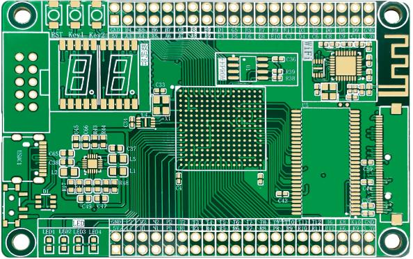
HDI | High-Density Interconnect, uses micro-vias. For space-constrained portable devices. | Min. Trace/Space: ≤0.075mm Laser Drilled Via Size: 0.1mm or smaller Stacked Via Structures: Any-layer interconnects |
|
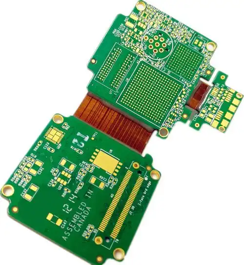
Flex/Rigid-Flex | Bendable, 3D assembly. Used in cameras, medical devices, wearables. | Substrate: Polyimide (PI) Bend Radius: A critical parameter Lamination Process: Complex for rigid-flex zones |
Rapid PCB prototyping is the process of quickly manufacturing a small quantity of printed circuit boards from design files for testing and validation purposes. It is important because it dramatically shortens the product development cycle, allowing engineers to identify and fix design issues early — before costly mass production begins — and accelerating the overall time-to-market.
With modern automated production lines, Laser Direct Imaging (LDI), and efficient logistics networks, standard rapid PCB prototypes can typically be delivered within 24 to 72 hours for simple boards (e.g., single-sided or double-sided FR-4). More complex boards such as HDI, high-frequency, or rigid-flex designs may require 5 to 10 business days depending on the specifications.
The industry-standard file format is Gerber (RS-274X), which includes individual layers such as copper layers, solder mask, silkscreen, and drill files (Excellon format). Most online PCB platforms also accept ODB++ or IPC-2581 formats. It is recommended to include a complete fabrication drawing (FAB drawing) specifying board thickness, copper weight, surface finish, and any special requirements.
The most common surface finish options include HASL (Hot Air Solder Leveling), which is the most economical choice; ENIG (Electroless Nickel Immersion Gold), preferred for fine-pitch components and high-frequency applications due to its flat surface and excellent signal quality; OSP (Organic Solderability Preservative), a lead-free and cost-effective option; and Immersion Silver or Immersion Tin for specific application requirements.
DFM stands for Design for Manufacturability. It is an analysis process that reviews your PCB design files to identify potential manufacturing issues — such as trace widths that are too narrow, insufficient clearances, improper drill sizes, or missing solder mask expansions — before fabrication begins. Conducting DFM analysis prior to prototyping helps prevent defective boards, reduces re-spin costs, and ensures a smoother transition from prototype to mass production.
Standard multi-layer PCBs use mechanically drilled through-hole vias to connect layers, with typical minimum trace/space of 0.1mm. HDI (High-Density Interconnect) PCBs use laser-drilled micro-vias (as small as 0.1mm or less), blind vias, and buried vias to achieve much higher routing density in a smaller board area. HDI technology is essential for compact, high-performance devices such as smartphones, wearables, and advanced medical equipment, but comes at a higher manufacturing cost and complexity.









