
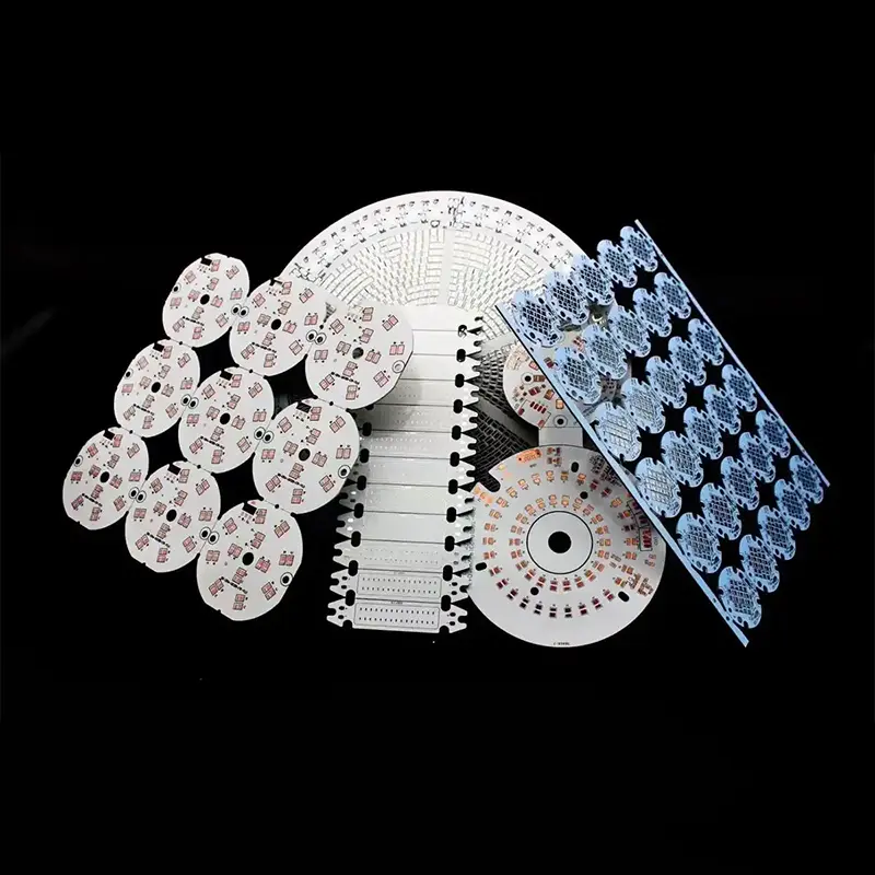
OEM High Thermal Conductivity Aluminum PCB from China Suppliers - Reliable Factory for Custom Solutions Factories, Factory
Product Description
| Structural Layer | Common Materials | Core Function |
|---|---|---|
| Circuit layer | Electrolytic copper foil ranging from 18 to 140μm | Make circuits and carry the welding of components |
| Insulating layer | Thermal conductive epoxy resin / ceramic filling adhesive | Insulation isolation + heat conduction (thermal conductivity 0.8–8W/m·K) |
| Metal base layer | Aluminum alloy (mainly 6061/5052) | The heat dissipation base quickly disperses the heat conducted by the insulation layer |
-
💡 LED Lighting
LED beads (especially high-power LEDs) generate concentrated heat. Aluminum substrates are the core substrates for street lamps, spotlights, and panel lights, which can keep the temperature rise of the beads within a safe range.
-
⚡ Power Electronics
Power modules (MOSFETs, IGBTs) of power adapters, frequency converters, and inverters need to dissipate heat quickly to prevent component burnout.
-
🚗 Automotive Electronics
On-board LED headlights, power controllers in the engine compartment, motor driver boards for new energy vehicles.
-
🔊 Audio Equipment
Power amplifier boards, audio power modules — reducing sound quality distortion caused by heat generation.
Ultra-High Heat Dissipation
The metallic thermal conductivity of aluminum plates can quickly transfer the heat generated by components (such as LEDs, power transistors) to the external heat dissipation structure, significantly reducing temperature rise and extending service life.
Lightweight + High Mechanical Strength
The density of aluminum alloy is much lower than that of copper and steel, and its bending resistance and impact resistance are superior to those of ordinary PCBs, making it suitable for portable and vehicle-mounted devices.
Good Dimensional Stability
The coefficient of thermal expansion (CTE) of aluminum alloy can be matched with components, reducing warping and solder joint cracking caused by temperature changes.
Insulation Safety
The insulation layer can withstand high voltage (common withstand voltage ≥3000V AC), preventing short circuits between the circuit and the aluminum plate.

Design Considerations
The heat dissipation pads need to be fully in contact with the aluminum plate: under the pads of high-power devices, "heat-conducting pads" should be designed and connected to the side of the aluminum plate through metallized vias (≥0.3mm) to enhance heat dissipation.
Line width adaptation current: Aluminum substrates are mostly used in high-current scenarios. The line width should be designed according to "1A current corresponding to 0.3mm line width (copper thickness 35μm)" to avoid heat generation.
Avoid burrs during aluminum plate cutting: Burrs on the edges of aluminum plates can easily puncture the insulation layer, so chamfering (≥0.5mm) treatment is required.

Manufacturing Process
Insulation layer bonding: High-temperature and high-pressure (180℃/3MPa) bonding is required to ensure that the insulation layer is free of bubbles and the peel strength is ≥1.0N/mm.
Surface treatment: Tin plating / nickel-gold plating is preferred, and OSP (organic film has poor heat resistance) should be avoided.
Forming method: CNC milling is adopted (instead of die-cutting for ordinary PCBs) to ensure the flatness of the aluminum plate edges.
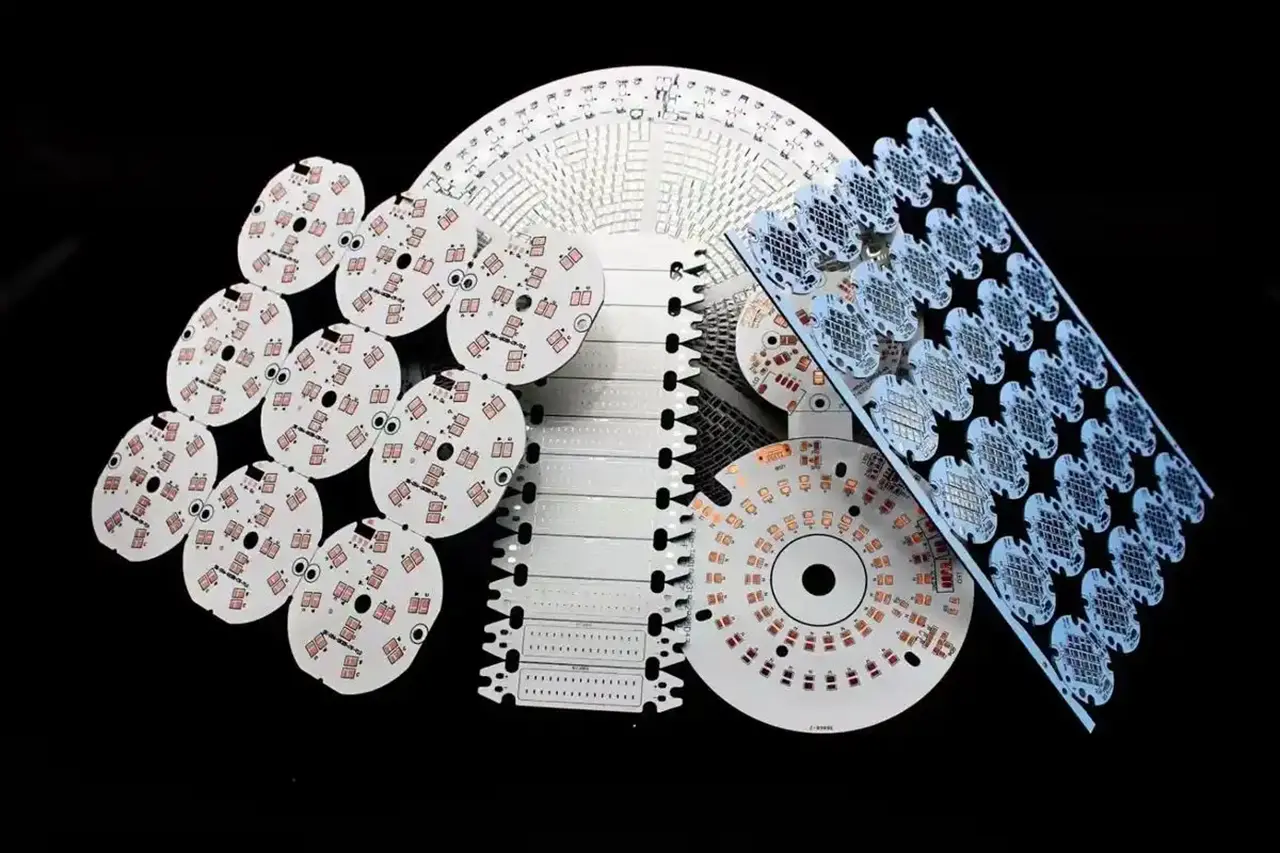
An aluminum PCB (also called an aluminum substrate or metal core PCB) uses an aluminum alloy base instead of the traditional FR4 fiberglass substrate. Its three-layer structure — circuit layer, insulating layer, and metal base layer — provides significantly superior heat dissipation, making it ideal for high-power and thermally demanding applications compared to standard PCBs.
The thermal conductivity of the insulating layer typically ranges from 0.8 to 8 W/m·K, depending on the material used (such as thermal conductive epoxy resin or ceramic filling adhesive). Higher thermal conductivity values are preferred for high-power applications to ensure efficient heat transfer to the aluminum base.
The most commonly used aluminum alloy grades for PCB manufacturing are 6061 and 5052. These grades offer an excellent balance of thermal conductivity, mechanical strength, lightweight properties, and machinability, making them well-suited for LED lighting, automotive electronics, and power module applications.
Tin plating and nickel-gold plating (ENIG) are the preferred surface treatment options for aluminum PCBs due to their excellent solderability and heat resistance. OSP (Organic Solderability Preservative) is generally not recommended because its organic film has poor heat resistance, which can be problematic in high-temperature environments.
For high-current scenarios, a general design guideline is: 1A of current should correspond to a minimum line width of 0.3mm when using a copper thickness of 35μm. Wider line widths reduce resistance and heat generation, which is critical for power electronics and LED driver applications where current loads are significant.
The insulating layer of a standard aluminum PCB is typically rated to withstand a voltage of ≥3000V AC. This high dielectric strength ensures safe electrical isolation between the copper circuit layer and the aluminum base, preventing short circuits and ensuring compliance with safety standards in power electronics and automotive applications.









