
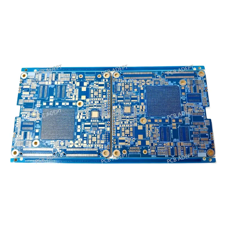
OEM China RF & Microwave PCB Suppliers - Low Loss, High Signal, Impedance Control for 500MHz+ Frequency Factory Solutions Companies, Quotes
Product Description
What is RF & Microwave PCB?
▶ The core is to control electromagnetic waves, treating PCB wires as transmission lines with characteristic impedance rather than simple electrical connections.
Three key design points
Never use ordinary FR-4. High-frequency dedicated boards with low loss and stable dielectric constant (such as Rogers RO4350B, RT/duroid series) must be selected. This is the cornerstone of performance.
Impedance and transmission lines: Precise 50Ω impedance control is essential. Use microstrip lines, striplines or coplanar waveguides and determine the precise line width through calculation/simulation. When laying out, minimize the paths and avoid right angles.
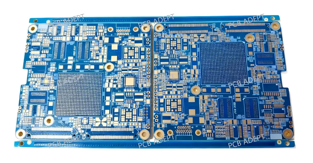
Provide a complete and solid ground plane to ensure a low-impedance return path.
Densely arrange grounding vias (especially on both sides of the transmission line) to suppress resonance and coupling.
Physically isolate the RF, digital, and power supply areas. When necessary, use shielding covers and via walls.
Key points of manufacturing
Strictly control the tolerance of line width and medium thickness.
ENIG gold plating is preferred to ensure flatness and high-frequency conductivity.
The solder mask layer may affect the impedance, and "window opening" treatment is often adopted for RF traces.
Conclusion
PCBADEPT Technology Company has extensive production experience in RF PCB manufacturing and RF PCB assembly, such as the production of anti-drone equipment, electronic fence equipment, walkie-talkies, etc.
RF PCBs play a very significant role in modern wireless communication devices, and an increasing number of customers are choosing such products.
Send inquiry
Frequently Asked Questions (FAQ)
Generally, Radio Frequency (RF) PCBs operate in frequencies ranging from 100 MHz up to 2 GHz, while Microwave PCBs operate in frequencies above 2 GHz and can extend to beyond 30 GHz.
Standard FR-4 exhibits a high dielectric loss (dissipation factor, Df) and an unstable dielectric constant (Dk) across varying frequencies and temperatures, which leads to significant signal attenuation and phase distortion in high-frequency applications.
A 50-ohm characteristic impedance represents the optimal historical and theoretical compromise between maximum RF power handling capacity and minimum signal attenuation (insertion loss) for coaxial and planar transmission lines.
Electroless Nickel Immersion Gold (ENIG) provides exceptional coplanarity and surface flatness for precise high-frequency trace geometries, prevents oxidation, and provides consistent electrical conductivity at the surface boundary where the skin effect is prominent.
Solder mask materials often possess a high and unpredictable dielectric loss at gigahertz frequencies. "Window opening" removes the solder mask directly above critical RF traces, eliminating dielectric loading and maintaining precise calculated impedance.
Key manufacturing tolerances include trace width control (often ±0.01mm or tighter), dielectric layer thickness uniformity, copper foil roughness control, and precise drill-to-copper registration for grounding via walls.









