
ODM China Raspberry Pi HAT: Top Suppliers and Factory Innovations for Mini Single-Board Computer Projects Quotes, Factories
Product Description
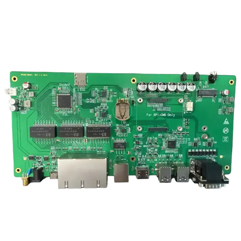
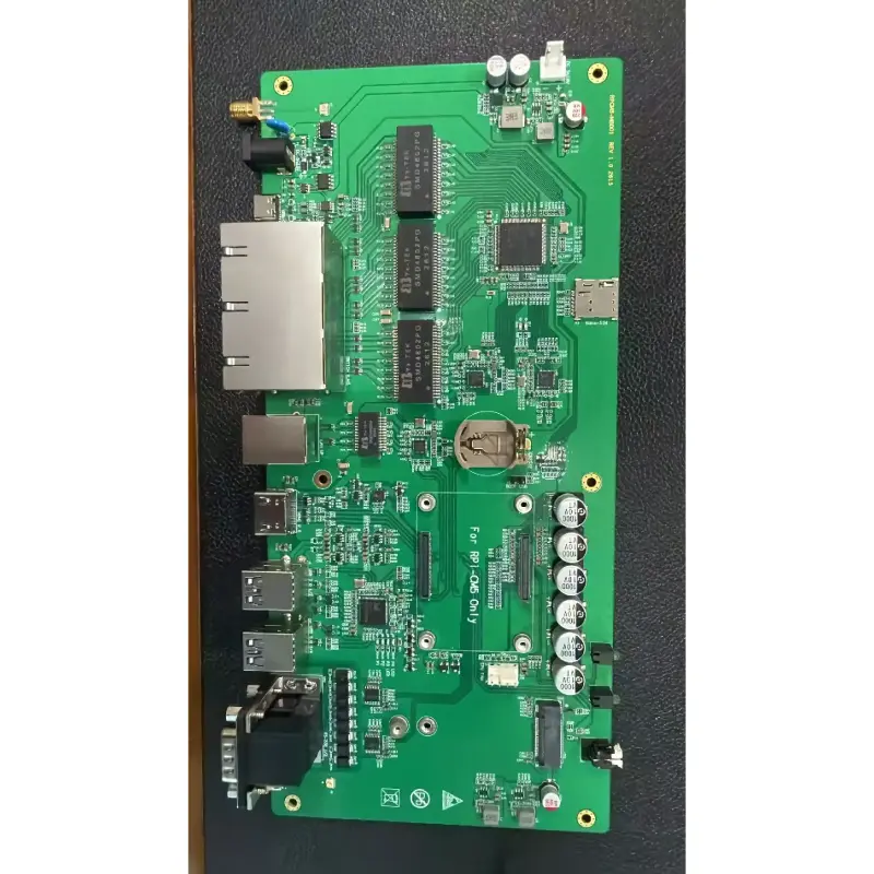
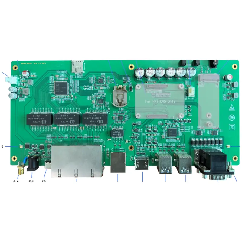
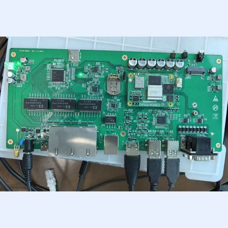
The product PCB measures 265×120 mm, with the top view shown below:
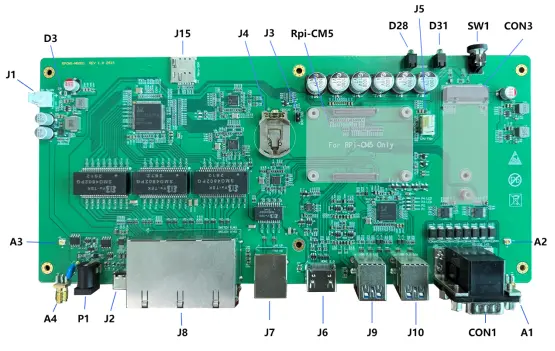
| Reference | Description | Reference | Description |
|---|---|---|---|
| J1 | Board-mounted power connector, DC 5–18V | J6 | HDMI 2.0 connector |
| P1 | External DC power supply, DC 5–18V | J9 | 2×USB Type-A connectors |
| J2 | USB Type-C fast charging, up to 20V | J10 | 2×USB Type-A connectors |
| Rpi-CM5 | Rpi-CM5 Core Board Connector | CON1 | 2×DB9 RS232 connector |
| CON3 | WAN (4G/5G) module connector | A1/A4 | SMA board external antenna connector |
| J15 | Nano-SIM card connector | A2/A3 | IPEX4-G1 board-mounted antenna connector |
| J4 | CR2032 battery connector | SW1 | System power switch button + CM5 indicator light |
| J5 | CM5 Fan Connector | D31 | WAN module indicator light |
| J3 | Firmware update jumper | D28 | User-defined indicator light |
| J8 | 6 GB switch Ethernet port | D3 | Power supply status indicator light |
| J7 | GB LAN Ethernet Connector |
Installation: Align the Rpi-CM5 module with the installation slot and place it flat. Gently press the module with your hand to ensure it sits properly in place. Avoid applying excessive force or forcing it down, as this may damage the connector or module. For permanent use, secure all four screw holes with M2.5 screws to prevent detachment during operation.
Disassembly: Remove the four fixing screws. Using a plastic pry tool, gently pry one edge not in contact with the connector (preferably the right side as shown in the view, i.e., the position of the fan connector), then lift it slightly upward until the module detaches from the slot; remove the module.
This product supports standard WWAN modules measuring 30×51 mm or 30×42 mm, featuring an M.2 B-Key interface with 67 pins and USB 3.0 communication.
The motherboard typically comes pre-installed with 30×51 modules. If users require 30×42 mm modules, a 3.0 mm-high M3 single-head fastening stud must be added to the board.
The user inserts the module at an angle into the M.2 slot. Once in position, gently press the module against the fixed hole for alignment, then secure it with M2.5 screws (M3 for 30×42 models).
This product features two sets of antennas—one internal and one external. The internal interface uses IPEX-G1, while the external interface employs SMA (internal hole). Users can install the appropriate antenna based on their specific requirements.
(1) CM5 WiFi and Bluetooth antennas: If the CM5 supports WiFi+BT functionality, a corresponding antenna must be installed. Purchase an IPEX-G1 to IPEX-G1 conversion antenna, inserting one end into the CM5's IPEX socket and the other end into the A2 or A3 connector on the board.
(2) WAN module antenna: WWAN module antennas typically come in one or more units, but this product supports up to two. Users must purchase the corresponding adapter cable (IPEX-G4 to IPEX-G1 or IPEX-G1 to IPEX-G1) based on the module's antenna interface, and plug both ends into the module's antenna connector and the internal A2 or A3 connector, respectively.
(3) External antenna on the installation panel: The external antenna should be selected based on the user's specific requirements (WiFi+BT or WAN 4G/5G). The antenna interface must be an SMA internal pin. Insert the antenna into the external antenna connector A1 or A4 and secure it firmly.
The SIM card is primarily designed to work with a WAN module for mobile communication. The SIM card slot is located at edge J15 on the board. This product only supports Nano-SIM cards.
Insertion: Insert the SIM card chip with its edge facing downward and the notch facing inward into the J15 slot, then gently push it inward until you hear the locking sound.
Removal: Gently push inward with your hand until the unlock sound is heard; the SIM card then pops out and can be removed.
This product provides a 2032 button battery connector (J4) to maintain the real-time clock operation of the Rpi-CM5.
Installation: Purchase a 2032 button battery of the appropriate model. Insert the battery according to the spring orientation, push it toward the locking position, and gently press downward until the battery engages with the locking mechanism.
Removal: Gently press the battery with your hand, then use pliers to pull the retaining tab backward until the battery pops out of the socket; remove it.
The product supports three power supply methods:
(1) Off-panel DC Power Supply
The external DC power supply can power the product through the P1 DC socket, supporting voltages of 5–18 V DC, with the plug core serving as the positive terminal and the outer ring as the negative terminal. If the external voltage exceeds 20 V, the system will enter a protection mode and automatically cut off the power supply.
(2) DC Power Supply Within the Panel
The J1 on the board is a VH (3.96) connector, providing an in-board DC power supply for interconnection and fully connected to P1. Its functionality and overvoltage protection are identical to those of the external DC power supply. Users must choose either the external or internal DC power supply method.
(3) USB Type-C Smart Fast-Charging Power Supply
The product supports power supply via J2 USB Type-C, with an input voltage range of 4V to 20V. It is compatible with PD3.2 EPR, AVS, PPS, SPR, and BC1.2 fast charging protocols, and features a built-in overvoltage protection module.
(4) Choice Between DC and USB Type-C Power Supply
The product supports both DC and USB Type-C power supplies simultaneously. The system automatically selects the higher-voltage source to provide power based on the voltage levels.
Before powering on, users should correctly insert all modules, ensure the PCB is installed inside the fixed chassis or placed in a secure position, and verify that no cables or components that may cause short circuits are present nearby. Connect a DC power source or a USB Type-C power source.
The user unplugs the external power source, including a DC power supply or a USB Type-C power adapter.
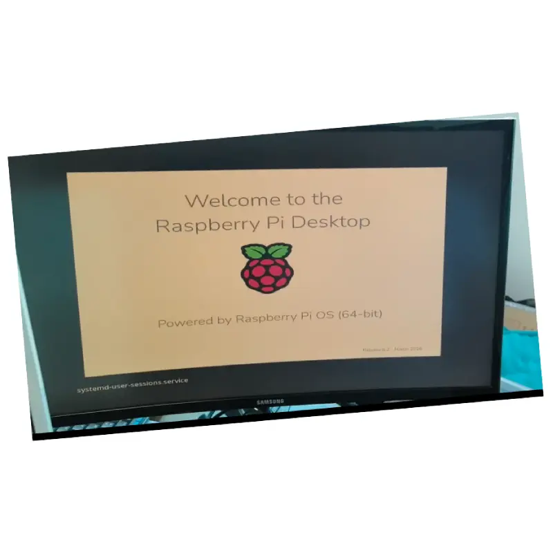
After powering on the system, it will start automatically.
When the system is powered on but in the shutdown state, press SW1 once to power it up.
After turning on the device, you should normally see the D3 light illuminate.
The system is operating normally. Users should first perform a shutdown operation in the system (e.g., the poweroff command), after which the system will shut down automatically.
Users can press the SW1 switch button once; the system will then display shutdown options, allowing them to choose to shut down.
Under special circumstances, users can perform a forced shutdown by pressing the SW1 switch button for 3 to 5 seconds.
After shutting down, the user can unplug the power supply.
When your Rpi-CM5 is a brand-new motherboard with no pre-installed system on its internal storage, you must first flash the firmware.
-
Preparations before burning:
This system uses a Windows host; users should first download the required software and prepare a data cable.
Download and install: rpiboot
Download and install: Raspberry Pi Imager
Data cable: A USB Type-A to USB Type-C data cable. -
Jumper wire:
When the power is off, set the jumper at position J3 to a short-circuit state by fitting the jumper cap. -
Insert a DC power supply:
Since the USB Type-C bus handles both power supply and data communication, the computer's output power is limited and may not be sufficient to power the Rpi-CM5. Therefore, a DC power supply is recommended. -
Connect the USB cable:
Insert the Type-C data cable's Type-C port into the product's J2 USB Type-C connector, and connect its Type-A port to the computer. After insertion, a new device named "BCM2712D0 Boot" appears in Device Manager under General Serial Bus Devices. -
Create a high-capacity USB storage device:
Run the "rpiboot – Mass Storage Gadget" from the rpiboot installation directory to initialize the previously identified USB device as a high-capacity storage device. -
Burn the firmware:
Run Raspberry Pi Imager, follow the prompts to enter the required information, and flash the firmware. Users can first download the corresponding firmware from their local image repository and then proceed with local firmware import for flashing. For the specific programming and flashing method, refer to the Raspberry Pi documentation until the process is complete. -
Return to normal operating mode:
After completing the burning, power off and set the jumper at position J3 to open circuit, or remove the jumper cap. After power restoration, the system will officially operate from the CM5 storage device.
In this system, the following functions do not require configuration:
✅ Switching Function: By default, the switching chip operates normally once properly powered.
✅ HDMI Functionality: Once the system is operating normally, the HDMI function works properly without requiring any additional configuration.
✅ USB-HUB Functionality: Once the system is operational, it automatically detects the USB-HUB feature, enabling all four sets of USB Type-A ports to function properly.
The features to configure include:
🔧 RS232 port functionality: The Rpi-CM5 does not default enable the corresponding UART function; kernel DTS configuration is required.
🔧 Required GPIOs: The system necessitates modifying the kernel DTS or performing corresponding configurations.
After properly powering on the device, first configure its WiFi function to establish network connectivity—ideally enabling internet access.
This product's LAN port (J7) employs the YT6801 chip and connects via the PCIe 2.0 interface of the Rpi-CM5 board.
Upon entering the system, using the lspci command reveals the device: "0001:01:00.0 Ethernet Controller: Motorcomm Microelectronics YT6801 Gigabit Ethernet Controller (Rev 01)."
The installation and deployment steps are as follows:
- Copy the driver (yt6801-1.0.31.tar.gz) to the product directory.
- Decompress driver:tar xvf yt6801-1.0.31.tar.gz
- Enter the driver directory:cd yt6801-1.0.31
- Install the driver:sudo ./install_yt6801-driver
- Check for error prompts until installation is complete.
Writing the MAC address: If you need to write the MAC address to the network card, follow these steps:
- Enter the yt6801-1.0.31 directory from the previous decompression step.
- Check that the Motorcomm_NIC_Burn_Helper program was generated during the previous installation step.
- Execute:sudo ./Motorcomm_NIC_Burn_Helper -index 0 -mac "MAC-ADDR"Index 0: The 0th device. This product has only one device, so it can only be 0.
The-mac "MAC-ADDR"parameter specifies the written MAC address, which can be separated by a-or colon:symbol.
Modify the /boot/firmware/config.txt file and add the following lines in Section [CM5]:
| Add Row | Use / Description |
|---|---|
dtoverlay=uart1-pi5dtparam=uart1=on |
Configure UART1 / Open UART1 |
dtoverlay=uart2-pi5dtparam=uart1=on |
Configure UART2 / Open UART2 |
dtoverlay=spi4-1cs |
|
dtoverlay=gpio-fan |
|
dtoverlay=act-led |
|
dtoverlay=gpio-shutdown,gpio_pin=17,active_low=1,gpio_pull=up |
Power monitoring, automatic shutdown |
gpio=0-7=a2 |
Configure GPIO 0–7 as the second function group |
gpio=14,15=op,dh |
WWAN AWREN and WWAN WDIS are configured to output a high level. |
gpio=16=op,dl |
The User_LED is configured to output a low level. |
gpio=17-21=ip |
PWR_GOOD, USBPn OC# configured as input |
gpio=22-27=pugpio=22-27=ip |
The LINK status indicator for switch ports (P1–P6) is set to high. The LINK status indicator for switch ports (P1–P6) is configured as input. |
tar xvf yt6801-1.0.31.tar.gz, enter the directory with cd yt6801-1.0.31, and run sudo ./install_yt6801-driver. After installation, if you need to write a MAC address, use the Motorcomm_NIC_Burn_Helper tool. Note that a MAC address can only be written once./boot/firmware/config.txt file and add the appropriate dtoverlay entries under the [CM5] section. For example, add dtoverlay=uart1-pi5 and dtparam=uart1=on to enable UART1, and similarly for UART2. GPIO functions such as power monitoring, LED control, and switch port LINK indicators also require corresponding gpio= entries in the same configuration file.








