
Famous Raspberry Pi HAT from China Factory: Top Suppliers for Mini Single-Board Computer and IoT Projects Pricelist, Factory
Product Description
1. PCB Installation View
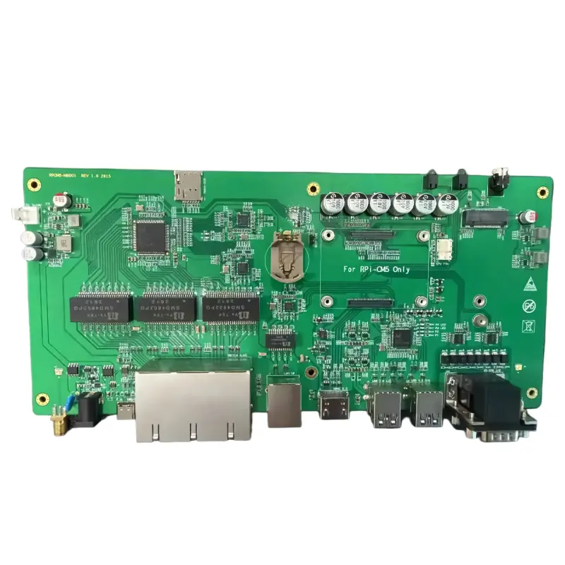
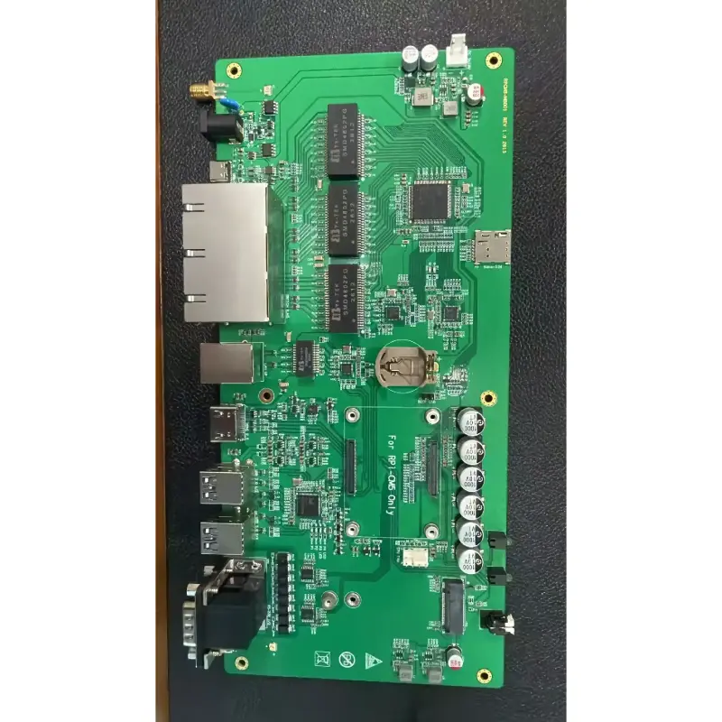
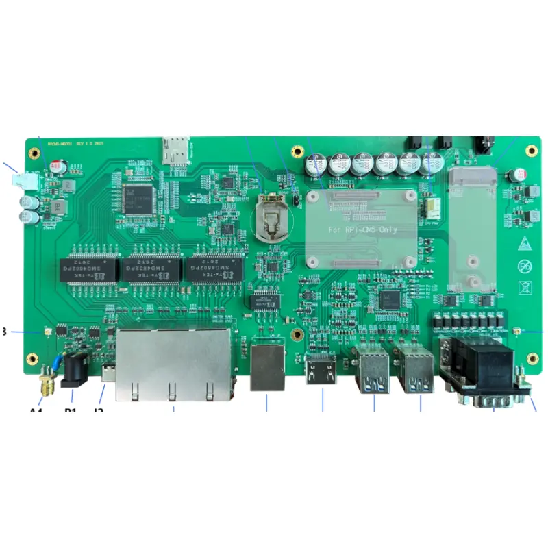
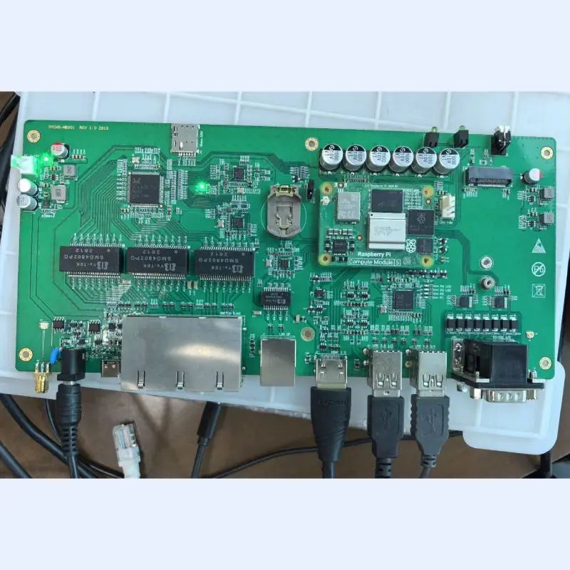
The product PCB measures 265x120 mm, with the top view shown below:
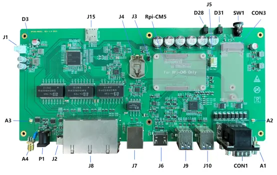
| Designator | Interface / Component Description | Designator | Interface / Component Description |
|---|---|---|---|
| J1 | Board-mounted power connector, DC 5–18V | J6 | HDMI 2.0 connector |
| P1 | External DC power supply, DC 5–18V | J9 | 2*USB Type-A connectors |
| J2 | USB Type-C fast charging, up to 20V | J10 | 2*USB Type-A connectors |
| Rpi-CM5 | Rpi-CM5 Core Board Connector | CON1 | 2*DB9 RS232 connector |
| CON3 | WAN (4G/5G) module connector | A1/A4 | SMA board external antenna connector |
| J15 | Nano-SIM card connector | A2/A3 | IPEX4-G1 board-mounted antenna connector |
| J4 | CR2032 battery connector | SW1 | System power switch button + CM5 indicator light |
| J5 | CM5 Fan Connector | D31 | WAN module indicator light |
| J3 | Firmware update jumper | D28 | User-defined indicator light |
| J8 | 6 GB switch Ethernet port | D3 | Power supply status indicator light |
| J7 | GB LAN Ethernet Connector | - | - |
2. Module Installation
2.1 Pre-Installation Notes
Note 1: Before installing any modules, ensure the motherboard is powered off. This product does not support hot-plugging for module installation.
Note 2: Wear anti-static gloves and never install the device with bare hands to prevent static electricity from damaging the motherboard or module chips.
2.2 Install Rpi-CM5
Installation: Align the Rpi-CM5 module with the installation slot and place it flat. Gently press the module with your hand to ensure it sits properly in place. Avoid applying excessive force. Secure all four screw holes with M2.5 screws for permanent use.
Disassembly: Remove the four fixing screws. Using a plastic pry tool, gently lift the edge not in contact with the connector until the module detaches.
2.3 Install the WAN Module
Supports standard WWAN modules (30x51mm or 30x42mm) via M.2 B-Key interface. Insert the module at an angle, press down, and secure with M2.5 or M3 screws.
2.4 Install the Antenna
(1) CM5 WiFi/BT: Use IPEX-G1 to IPEX-G1 conversion antenna between CM5 and A2/A3 connectors.
(2) WAN Module: Connect module antenna ports to board connectors A2 or A3 using appropriate adapter cables.
(3) External: Secure SMA internal pin antennas to connectors A1 or A4.
2.5 Install the SIM Card
The J15 slot supports Nano-SIM cards only. Push in until it locks; push again to eject.
2.6 Install the Real-Time Clock Button Battery
Use a 2032 button battery at J4. Insert according to spring orientation. Note: Remove battery before installing/removing other modules.
3. Power Supply and On/Off Operation
3.1 Power Supply Method
(1) Off-panel DC: P1 socket (5–18 V DC). Center positive.
(2) In-board DC: J1 VH (3.96) connector, identical to P1.
(3) USB Type-C: J2 supporting 4V–20V and various fast-charging protocols (PD3.2, PPS, etc.).
The system automatically selects the source with higher voltage if both are connected.
4. Power On and Off
Power On: System starts automatically upon power connection. If in shutdown state, press SW1. D3 light indicates power.
Power Off: Use system command (poweroff) or press SW1 for shutdown options. Forced shutdown: Hold SW1 for 3-5 seconds.
5. Burn the Firmware
- 1 Install rpiboot and Raspberry Pi Imager on a Windows host.
- 2 Set jumper J3 to short-circuit state.
- 3 Connect DC power and USB Type-C cable to computer.
- 4 Run "rpiboot – Mass Storage Gadget" to initialize storage.
- 5 Use Raspberry Pi Imager to flash the firmware.
- 6 After flashing, remove J3 jumper and reboot.
6. Relevant System Configuration
6.1 Default Features
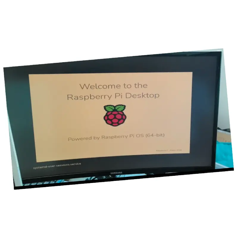
HDMI, Switching, and USB-HUB functions work by default. Driver installation is required for LAN port (YT6801) and RS232.
| Config Line (config.txt) | Usage & Description |
|---|---|
| dtoverlay=uart1-pi5 / dtparam=uart1=on | Configure & Open UART1 |
| dtoverlay=uart2-pi5 / dtparam=uart1=on | Configure & Open UART2 |
| dtoverlay=gpio-shutdown,gpio_pin=17... | Power monitoring, auto shutdown |
| gpio=0-7=a2 | Configure GPIO 0-7 function group |
| gpio=14,15=op,dh | WWAN AWREN/WDIS output high |
| gpio=22-27=ip | Switch port LINK status input |
Send Inquiry
Frequently Asked Questions
The PCB measures 265x120 mm.
No, the device does not support hot-plugging. Always ensure the motherboard is powered off and the button battery is removed before module installation.
It supports DC 5-18V via the DC socket/VH connector and 4V-20V via USB Type-C smart fast charging.
The board features a J15 slot designed specifically for Nano-SIM cards.
In special circumstances, press and hold the SW1 switch button for 3 to 5 seconds to force the system to shut down.
No, the YT6801 Gigabit Ethernet chip requires a specific driver installation (yt6801-1.0.31) to function on the Rpi-CM5.









