

Buy Heavy Copper PCB Manufacturer in China - Reliable Suppliers for Power Converters with Superior Heat Dissipation Manufacturers, Supplier
Product Description
- Strong current-carrying capacity: The current-carrying capacity of 70μm copper foil (2 oz) is approximately twice that of 35μm copper foil (1 oz) under the same line width.
- Good heat dissipation: The thick copper layer can quickly conduct heat, reducing the risk of overheating of the device.
- High mechanical strength: Thick copper enhances the PCB's resistance to bending and impact.
- Power converters (AC-DC / DC-DC)
- BMS for new energy vehicles
- Industrial frequency converters
- Control boards for welding machines
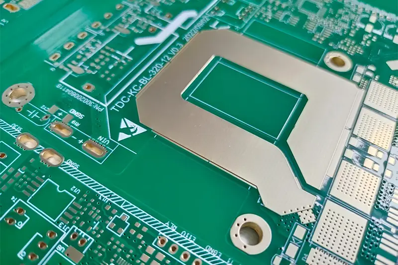
Selection of Copper Foil Thickness
- Common specs: 70μm (2 oz), 105μm (3 oz), 140μm (4 oz), up to 420μm (12 oz)
- For large current (≥5A): prefer 2–4 oz copper
- For ultra-power (≥20A): select 6–12 oz copper
Trace & Current-Carrying Capacity Design
- Formula reference: I = K × W × T0.83
- Example: 2 oz copper (70μm), wire width 5mm → ~15A (ΔT 10℃)
- Keep high-current traces short and wide; avoid narrow necks
- Multi-layer boards: parallel copper layers (e.g., 2×2 oz = 4 oz equivalent)
Via & Pad Design
- High-current vias: hole diameter ≥0.5mm, increase via count (~1A per hole)
- Hole wall copper plating ≥20μm (vs. 8–12μm for standard PCBs)
- Thick copper pads: enlarge by 0.2–0.5mm to prevent false soldering
Heat Dissipation & Insulation Design
- Design thick copper area as a "copper sheet heat sink"
- Add metallized via array (spacing ≤1mm) to connect heat dissipation layer
- For 70μm copper: wire spacing ≥0.2mm to prevent creepage breakdown under high voltage
Thick copper lamination requires high-temperature and high-pressure lamination (180℃ / 4MPa) to ensure peel strength between copper foil and substrate (≥1.2N/mm).
Thick copper etching: Etching rate is slow (~1μm/min). Etching time must be controlled to avoid side etching (side etching ≤0.05mm). A stepwise etching process should be adopted to reduce line width deviation.
The CTE of thick copper layers differs significantly from that of the substrate. A "symmetrical structure" (consistent copper thickness between upper and lower layers) should be adopted during lamination, and a rigid support layer should be added to prevent PCB warping (warping degree ≤0.5%).
Thick copper surfaces are prone to oxidation. Tin plating (high-temperature tin layer) or nickel-gold plating is preferred over OSP (which may result in incomplete organic film coverage).
The pad area needs an enlarged "solder mask opening window" to ensure proper bonding force between solder and thick copper.









